EBTS
Introduction
- No LST! (No Red Lights on TSC, and No Annoying Notification on the Front of your Radios)
- Network Wide Group Calling - TGS Configured in our Core are Routed between ALL Linked BTS Sites
- Local Site Private Calling - Having a Linked site allows for 1-1 Private Calling (NOT FULL DUPLEX). Simply Dial the ISSI Number of the radio you wish to dial and hit PTT, this will call the radio and establish a 1-1 Call
- Wide Area Private Calling - As Above, Just across the network! - Call your buddys across the world via their ISSI Number.
The aim of this guide is to help you get your EBTS connected to our Virtual Core, and enjoy all TETRA features (+ TPC interconnects, coming soon™).
Disclaimer
-
Follow this guide at your own risk! This is an experimental bridge, and we can't be held responsible if anything bad happens to your precious EBTS!
-
DEBIAN/RASPBIAN WITH A GUI IS NOT SUPPORTED! - PLEASE ENSURE YOU INSTALL DEBIAN LITE (NO GUI), THIS IS KNOWN TO CAUSE OUT OF RESOURCE BUGS WITH OSMO-E1D
-
Supplied Configurations for Cisco Connectivity are Examples/Known Working Configurations, it is down to the Site Sysop to Secure their own System from unauthorised access
Prep Work
- Before starting this endeavor, get in touch with the Core Network Team, you'll need some specific configurations files for your site (Cisco and EBTS)
- You must have a basic understanding of the TETRA standard (how it behaves, how to program radios with MCC/MNCs, add talkgroups).
- Modifications on the EBTS settings will also be needed, make sure you're also feeling at ease with that.
- Some Linux Console knowledge as well as basic Cisco usage will also come in handy.
Connection methods
Option 1 - Cisco router
- A working EBTS/MBTS setup in lone site trunking mode (bare minimum: Base Radio + Site Controller). Don't forget an RS-232/USB converter if your computer doesn't a native DB9 connector!
- Raspberry Pi. You can also use a Mikrotik router, but this is not documented here (you'll need to install and configure ZeroTier, and bridge it to a LAN port).
- Cisco 1900 / 2600 Series router + E1 Card (either one or two ports, both will work). You'll also need an additional Ethernet USB Dongle for the Pi. Make sure you also have a console cable.
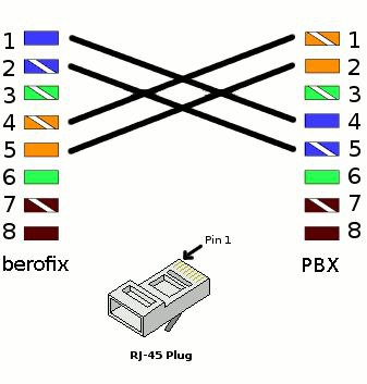
- An E1 Crossover cable (RJ45 plugs). Schematic is as follows:
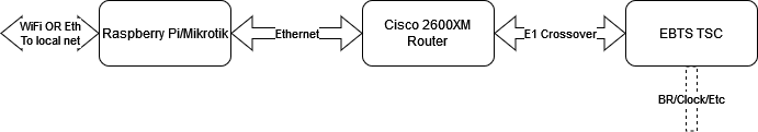
The complete setup will look like this:
Raspberry Pi Setup
- Prepare an SD Card with a 64-Bit version of Raspberry OS Lite(Bookworm being the latest, We Don't Need a GUI). Don't forget to configure SSH and WiFi if you plan to use it. You can also use an additional USB/Ethernet dongle instead of Wifi (you'll need an available ethernet port to connect to the Cisco Router either way).
- Update/Upgrade the OS after boot:
sudo apt get update && sudo apt upgrade reboot - Download and run the following configuration script. This will create the bridging interface, and add you to the ZeroTier network:
wget https://packages.tetrapack.online/install/tools/EBTS/CiscoBridge.sh | sudo bash - Connect the USB-Ethernet dongle if needed, and reboot. Connect the Cisco Router FastEthernet0/0 port to the dongle, and your WAN network to the Pi's onboard jack (or to the main Pi Ethernet jack if you're using Wifi to get online).
Sometimes the Pi will pick either the internal Eth or the Dongle Eth to be Eth0. If you notice that you cannot get a connection via your LAN to the Pi, try swapping the connection to the Cisco over.
Cisco Router Setup
- Connect your computer to the Console port of the router (via either an USB/RS232 adapter or a native DB9 port if you're lucky enough to still have one). Open up your favourite terminal program (I personally use putty) at 9600 baud.
- Follow these steps to reset your router to factory defaults.
- Once you finish step 8 on this before-mentioned guide, type "no" then enter.
- Check your Firmware Version:
show version Cisco IOS Software, C2600 Software (C2600-IPBASEK9-M), Version 12.4(12), RELEASE SOFTWARE (fc1) is Required - If you see any other version than what's mentioned above, reach out to one of the Core Network Team to update it.
- Open the Cisco Router config file you received (see "Prep Work") and copy its content (Ctrl+C). Enable the console and enter configuration mode:
config t Ctrl+V (paste) end write mem - Once done, you should be able to ping the Core via:
ping 192.168.250.254 - Almost there! If for some reason your FastEthernet0/0 interface didn't go up, type:
config t
int Fast0/0
no shutdown
end
write mem
Option 2 - icE1usb interface
Please read article FrameRelay-over-E1 Daemon (FRED)
After FRED install please edit /opt/FRED/default.env and run following command:
sudo /opt/FRED/dimetra-setup.shEBTS Site Controller
- Connect a USB/RS232 (or native DB9, again) from your computer to the service access port of the TSC. Open up BTS Service Software (aka TESS), select Dimetra R8. Password is Sys*mgr123$%. Under Configuration ==> Direct Settings, make sure you selected the right COM Port.
- Select Connection ==> Connect Direct. Turn on the TSC and wait for it to boot up completely. If it's already on, just press on enter, you should get a prompt for a user/password. Defaults should be factory/factory.
- Select Upload Configuration, and download the latest file from the Site Controller. Once done, close the connection via Connection ==> Close Connection.
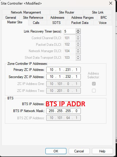
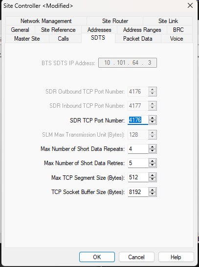
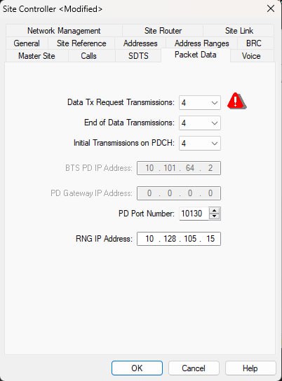
- Open the TSC Configuration file you just pulled via File ==> Open. Edit the Site Configuration via Personality ==> Modify. Click on "Edit Site Controller"
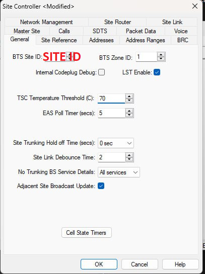
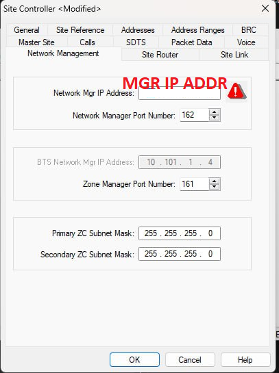
- From the Core Team, you should have received the following data: Site ID, BTS IP Address, PVC Primary, PVC Backup and Network Mgr IP Address. Make sure you have them close by, you'll need them now.
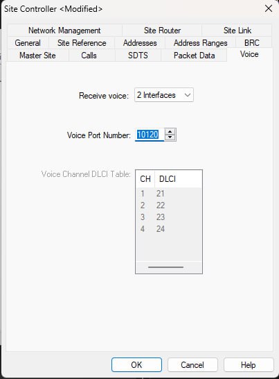
- Check your configuration matches the screenshots below, and copy over your site-specific data:


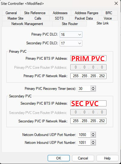
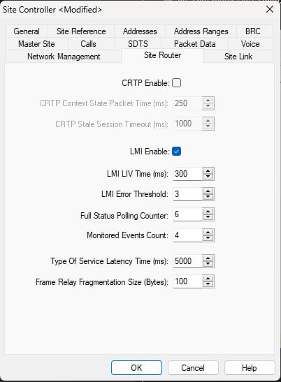

- Once you're finished, double check everything. Save the file, and reconnect to the TSC (Connection ==> Connect Direct).
- Click on Connection ==> Send Files. Select "Configuration Files" and select the file you just saved. In the “File Download” window, enter a version label, check “Use Next” and click on “Update Selected Items”. Press OK to start the transfer. You'll get a prompt to select which configuration file to replace. Select the one with all the minus signs.
- Remember when uploading the new configuration to update the "Use Next" Flag
- Reset the TSC by issuing the "reset" command on the terminal. Wait for the reboot, and log yourself in again (with factory/factory)
- Type the following commands to enable Site Link:
.sitelink -e1 .e1config -crdStart 1 -crd 31 -ts16Skip off -portNo 1 -crc on reset - After reboot, your TSC should now be connected to the Core Network! Enjoy :)


Final Steps
Once you have connected your BTS to the Core Network, Please go to https://map.tetrapack.online and register your user.
When an admin approves your user, you can log in and add your BTS to the map!
You will need the following information available when registering your BTS:
Zerotier Client ID: you will get this when setting up your Pi for Either Cisco or FRED configuration.
TX Frequency
RX Frequency
Duplex Table
Duplex Spacing
Once the BTS is approved by an Admin it will appear automatically on our BTS Map!
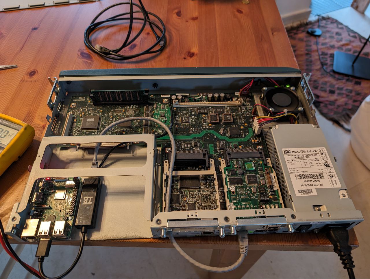
Cable Management Mod for Option 1
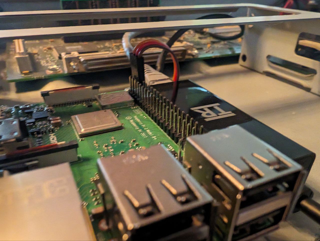
I found it quite convenient to put the Pi inside the empty Primary Network Module slot. A small mounting plate with double sided tape, another one for the USB/Eth dongle, and it's already much cleaner!
Bonus points if you use the Cisco Router's power supply to supply 5V to the Pi! Just solder a couple of wires on the edge card connector at the front of the router's mainboard. Leftmost pin is GND, then 12V (don't solder there!) then 5V. Double and triple check with a multimeter before hooking the Pi up.
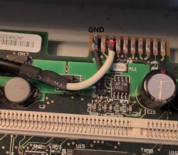
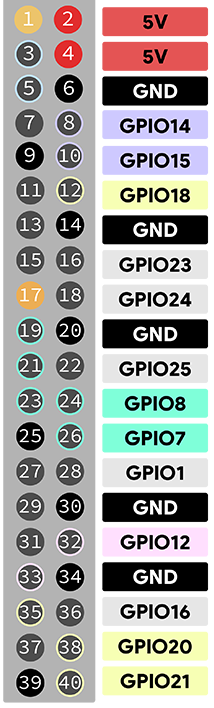
Pins 2 and 6 on the Pi can respectively be used as 5V and GND. An old servo connector does the job quite well!
No comments to display
No comments to display