TETRA
- Motorola
- Setting up Dummy and LogCollector for a TETRAPack connection
- EBTS
- Dummy
- CTS Log Collector
- MTS
- CTS Updater
- CTS
- SmartConnect
- Rohill
- Hytera
- Interfacing
- Radio Settings
- Server Bridging
- Compatibility Chart
- Specifications
Motorola
Setting up Dummy and LogCollector for a TETRAPack connection
Disclaimer
-
Please note you follow this guide at your own risk! This is an experimental bridge, and we can't be held responsible if anything bad happens to your precious CTS!
-
This guide is for a Single-BS (one CTS) subnet. If you wish to interconnect more CTSes locally, you'll need to modify the network topology + E1 time slotting accordingly.
Hardware requirements
- Raspberry Pi (4 is ideal, 2GB is ok), with PSU and SD card
- icE1USB
- A USB-Ethernet Adapter
- A CTS (DUH)
Prep work
- Make sure you understand how TetraPack works, its topology, how Dummy and LogCollector operate with each other, etc.
- Before going any further, read this!
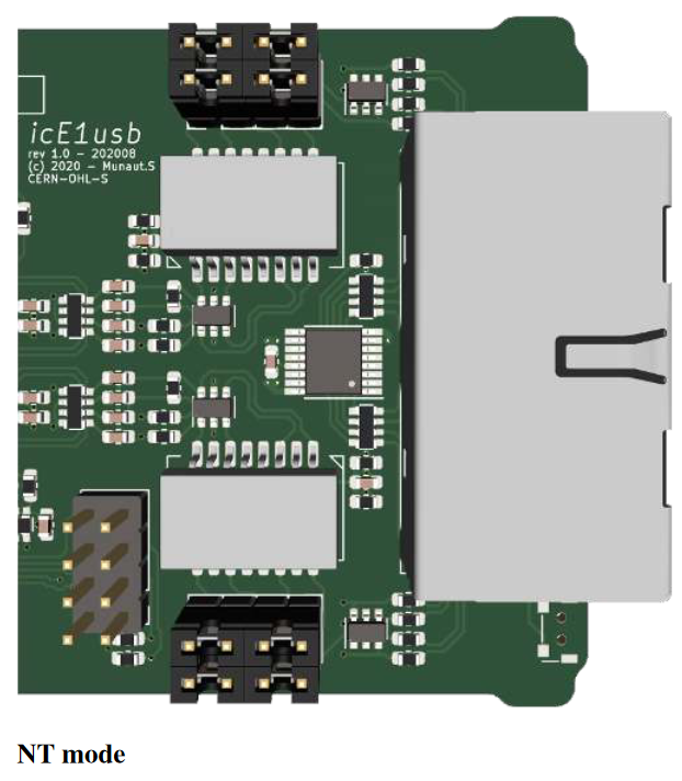
- Open up the icE1USB (from the back, with the SMA connector), and swap the jumpers so they match this picture:

CTS Setup
- Get a clear view of how the CTS is configured, and its necessary configuration files: bssparams.txt, set_x_gp, gm, sc, sub.csv, etc. Please make sure everything works as a standalone site before starting this entire endeavour!
- You also need good way to remotely connect to the CTS management interface (VNC is a good option).
- Plan ahead and make a list of the BrandMeister TGs you want your CTS to handle. Add them already to set_x_gp and gm.csv, reboot everything and make sure they already work locally in standalone mode.
- Open up bssparams.txt on your CTS, and do the following edits. Don't change anything else at this state:
## Base-Station Parameters ################################################################ #### Set the name to something simple, short, no special caracters /base-station/name = "CTSBS"; #### set this to id 1 /base-station/base-station-id = 1; #### add or replace: /base-station/standalone-mode = false; #### add or replace: /base-station/use-local-site-fall-back = false; ## Air Interface BLE Parameters ########################################################### /base-station/BLE/neighbour-cells = 191; ## SDS Gateway Parameters ################################################################# #### Remove all other lines, replace by: /system/sds-gateway/host-1 = { issi = 262999; ip-address = "44.225.64.18";}; /system/sds-gateway/host-2 = { issi = 250999; ip-address = "44.225.64.19";}; /system/sds-gateway/host-3 = { issi = 16777184; ip-address = "44.225.64.20";}; # These ISSIs will be used for SMS and GPS services (via GWPC emulation, IP addresses don't matter) ## E1 Layout Parameters ################################################################### ### Remove all other E1 layout lines, and replace byt this: /network/E1-layout/time-slot-01 = { source-type = "SIGNALLING"; }; /network/E1-layout/time-slot-02 = { source-type = "SIGNALLING"; }; /network/E1-layout/time-slot-03 = { source-type = "SIGNALLING"; }; /network/E1-layout/time-slot-04 = { source-type = "SIGNALLING"; }; #### Real BS transceivers /network/E1-layout/time-slot-17 = { source-type = "BS"; base-station-id = 1; l-transceiver-id = 11; }; #### Dummy's emulated BS transceivers /network/E1-layout/time-slot-22 = { source-type = "BS"; base-station-id = 8; l-transceiver-id = 11; u-transceiver-id = 12;}; /network/E1-layout/time-slot-23 = { source-type = "BS"; base-station-id = 8; l-transceiver-id = 13; u-transceiver-id = 14;}; /network/E1-layout/time-slot-24 = { source-type = "BS"; base-station-id = 8; l-transceiver-id = 15; u-transceiver-id = 16;}; /network/E1-layout/time-slot-25 = { source-type = "BS"; base-station-id = 8; l-transceiver-id = 17; u-transceiver-id = 18;}; #### Dummy's emulated GWPC encoders /network/E1-layout/time-slot-26 = { source-type = "DISP"; }; /network/E1-layout/time-slot-27 = { source-type = "ISDN"; }; /network/E1-layout/time-slot-28 = { source-type = "ISDN"; }; /network/E1-layout/time-slot-29 = { source-type = "ISDN"; }; /network/E1-layout/time-slot-30 = { source-type = "ISDN"; }; ## Network Topology Parameters ############################################################ #### Remove all other network topology parameters, and replace by this. Don't forget to change CTSNAME to the same name as in line 3! /network/topology/gateway-pc = { name = "Gateway Server"; E1-connection-1 = "BS-8"; }; /network/topology/base-station-1 = { name = "CTSBS"; E1-connection-1 = "BS-8"; }; /network/topology/base-station-8 = { name = "DUMMY"; E1-connection-1 = "BS-1"; E1-connection-2 = "GW-PC"; }; - Save and reboot the CTS, make sure it still works.
- Copy bssparams.txt over to your local PC, you'll need it for your Raspberry Pi.
- Write down the IP address of your CTS BSC computer (mine was 10.10.15.31, but yours will probably be different).
Software Stack Install
- Prepare an SD card with a 64-bit Raspbian Bookworm (Debian 12)
- Update/Upgrade the OS after boot:
sudo apt update && sudo apt upgrade reboot - Add the Osmocom repo, as per Osmocom's documentation:
sudo su OSMOCOM_REPO="https://downloads.osmocom.org/packages/osmocom:/latest/Debian_12" wget $OSMOCOM_REPO/Release.key mv Release.key /etc/apt/trusted.gpg.d/osmocom-latest.asc echo "deb [signed-by=/etc/apt/trusted.gpg.d/osmocom-latest.asc] $OSMOCOM_REPO/ ./" > /etc/apt/sources.list.d/osmocom-latest.list apt update - Install Osmocom E1D:
sudo apt install osmo-e1d - Add the TetraPack repository:
wget https://packages.tetrapack.online/install/public.key mv public.key tetrapack.asc sudo apt-key add tetrapack.asc sudo echo "deb [arch=arm64] http://packages.tetrapack.online/repository/ bookworm main" > /etc/apt/sources.list.d/tetrapack.list sudo apt update - Install TetraPack dummy and cts-logcollector
sudo apt install tetrapack-dummy cts-logcollector - Plug in the icE1USB to your Rpi, recover the interface serial number:
sudo lsusb -d 1d50:6145 -v 2> /dev/null | grep iSerial - Open (with for instance nano) /etc/osmocom/osmo-e1d.cfg, copy/paste this:
log syslog daemon e1d interface 0 icE1usb usb-serial [interface serial number] line 0 - Reload the service:
sudo systemctl restart osmo-e1d
Dummy - E1 Link setup
- Make sure Dummy is off with:
sudo systemctl stop dummy@default.service - Open/Create /opt/TetraPack/bssparams.txt, and copy/paste the contents from the file created at the CTS setup step. Edit the following lines
## System Parameters ##################################################################### ### Edit/Replace /system/name = "DUMMY"; ## Base-Station Parameters ################################################################ ### Edit/Replace /base-station/name = "DUMMY"; /base-station/base-station-id = 8; - Open/Create /opt/TetraPack/default.env
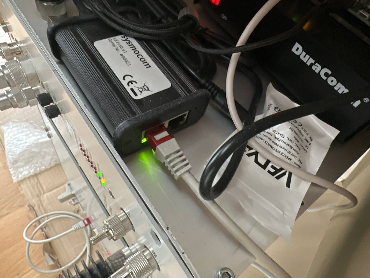
# E1D interface and line in format [interface number].[line number] DUMMY_LINE=0.0 # Path to CTS topology file (bss3.txt or bssparams.txt) DUMMY_TOPOLOGY=/opt/TetraPack/bssparams.txt # IP address and mask for CTS VTUN interface DUMMY_NETWORK="192.168.0.8 mask 255.255.255.0" # Specific options (multiple values can be delimited with comma): # replace-forwarded-link-status - replace IP-forwarded status for both E1 lines status of local BSs/GWPC to up # emulated-bs-line1-down - set E1-1 status of emulated BS to down # emulated-bs-line2-down - set E1-2 status of emulated BS to down # emulated-gwpc-line1-down - set E1-1 status of emulated GWPC to down # emulated-gwpc-line2-down - set E1-2 status of emulated GWPC to down DUMMY_OPTION= # Server connection URI in format http(s)://[user]:[password]@[address]/[path and parameters] # If you care about securely stored password, please put credentials into /opt/TetraPack/.netrc (man netrc) # REPLACE <YOUR DMR-ID> and <YOUR HOTSPOT/REPEATER PASSWORD> with your radio ID and password :) DUMMY_CONNECTION="http://<YOUR DMR-ID>:<YOUR HOTSPOT/REPEATER PASSWORD>@core.tetrapack.online:8081/dummy/?mode=bs+gwpc" # Instance name for D-BUS IPC interface DUMMY_INSTANCE=default - Save everything, cross your fingers and connect E1.1 from your BSC to the left port of icE1usb, like so:

- The matching LED on the port should stop blinking, and the red LED on E1-1 should turn off.
- Try to start dummy from the console:
cd /opt/TetraPack ./run.sh default.env # First, read starup messages and check that configuration (default.env and bssparams.txt) parsed successfuly # Second, check connection: if you see, in blue, "Q.921 connection established", congratulations! Your E1 link works! # You should also see "Socket Connection Established" - this means, connection to server established - If everything works, Ctrl+C to stop the console instance, and enable the service + start it
sudo systemctl start dummy@default.service
LogCollector - CTS Management interface setup
- Connect the USB/Ethernet interface to the Pi, and connect an Ethernet cable from BSC management port to the usb dongle.
- Stop LogCollector:
sudo systemctl stop cts-logcollector@default.service - Set a static IP on the interface (probably eth1) on the same range as the BSC, by editing /etc/dhcpcd.conf and adding this:
# Don't forget to edit your ip address to match the range of your BSC! interface eth1 static ip_address=10.10.15.20 static routers=10.10.15.1 - Test if you can connect via telnet:
telnet [BSC IP ADDR] 51600 #If you get "220 Network Management Interface is ready.", you're good to go! - Through that telnet interface, you can check if you got a good E1 link with Dummy:
login a cd network netstat #Look at the table that pops up, and focus on the "Links" column #260-rsp #260-Node Links DD AI ISDN DISP #260--------------------------------------------- #260-BS-1 u - u u - - #260-BS-2 ? ? ? ? - - #260-BS-3 ? ? ? ? - - #260-BS-4 ? ? ? ? - - #260-BS-5 ? ? ? ? - - #260-BS-6 ? ? ? ? - - #260-BS-7 ? ? ? ? - - #260-BS-8 u u u u - - #260-GWPC d u u - u d #260- #260 . #BS-1 should have first link on U, BS-8 should have both U, and GWPC should have D U #If it's not the case, check the topology with: cd topology ls #Should show this: #260- d-- gateway-pc #260- d-- base-station-1 #260- d-- base-station-8 #If not, check your bssparams.txt on both the CTS and the Pi, something is wrong. - Close the Telnet session (Ctrl+c), open /opt/LogCollector/default.env, and change the ip address:
# [IP of basestation] [dummy instance name] [basestation ID (1-8)] COMMAND_ARGUMENTS=[YOUR BSC IP] default 1 - Enable/Restart LogCollector, wait for a bit and see if you get data coming from the CTS when you place a call or attach to a group:
sudo systemctl enable cts-logcollector@default.service sudo systemctl start cts-logcollector@default.service #Let's monitor syslog to see if it recovers logs from the CTS. You should see a bunch of lines show up. tail -f /var/log/syslog | grep cts - If it works, great! LogCollector is ready. Ctrl+C to quit tail, carry on to the rest
EBTS
Introduction
- No LST! (No Red Lights on TSC, and No Annoying Notification on the Front of your Radios)
- Network Wide Group Calling - TGS Configured in our Core are Routed between ALL Linked BTS Sites
- Local Site Private Calling - Having a Linked site allows for 1-1 Private Calling (NOT FULL DUPLEX). Simply Dial the ISSI Number of the radio you wish to dial and hit PTT, this will call the radio and establish a 1-1 Call
- Wide Area Private Calling - As Above, Just across the network! - Call your buddys across the world via their ISSI Number.
The aim of this guide is to help you get your EBTS connected to our Virtual Core, and enjoy all TETRA features (+ TPC interconnects, coming soon™).
Disclaimer
-
Follow this guide at your own risk! This is an experimental bridge, and we can't be held responsible if anything bad happens to your precious EBTS!
-
DEBIAN/RASPBIAN WITH A GUI IS NOT SUPPORTED! - PLEASE ENSURE YOU INSTALL DEBIAN LITE (NO GUI), THIS IS KNOWN TO CAUSE OUT OF RESOURCE BUGS WITH OSMO-E1D
-
Supplied Configurations for Cisco Connectivity are Examples/Known Working Configurations, it is down to the Site Sysop to Secure their own System from unauthorised access
Prep Work
- Before starting this endeavor, get in touch with the Core Network Team, you'll need some specific configurations files for your site (Cisco and EBTS)
- You must have a basic understanding of the TETRA standard (how it behaves, how to program radios with MCC/MNCs, add talkgroups).
- Modifications on the EBTS settings will also be needed, make sure you're also feeling at ease with that.
- Some Linux Console knowledge as well as basic Cisco usage will also come in handy.
Connection methods
Option 1 - Cisco router
- A working EBTS/MBTS setup in lone site trunking mode (bare minimum: Base Radio + Site Controller). Don't forget an RS-232/USB converter if your computer doesn't a native DB9 connector!
- Raspberry Pi. You can also use a Mikrotik router, but this is not documented here (you'll need to install and configure ZeroTier, and bridge it to a LAN port).
- Cisco 1900 / 2600 Series router + E1 Card (either one or two ports, both will work). You'll also need an additional Ethernet USB Dongle for the Pi. Make sure you also have a console cable.
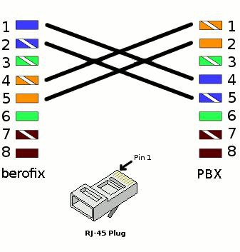
- An E1 Crossover cable (RJ45 plugs). Schematic is as follows:
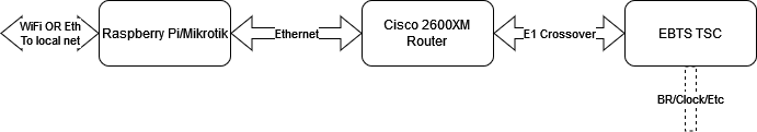
The complete setup will look like this:
Raspberry Pi Setup
- Prepare an SD Card with a 64-Bit version of Raspberry OS Lite(Bookworm being the latest, We Don't Need a GUI). Don't forget to configure SSH and WiFi if you plan to use it. You can also use an additional USB/Ethernet dongle instead of Wifi (you'll need an available ethernet port to connect to the Cisco Router either way).
- Update/Upgrade the OS after boot:
sudo apt get update && sudo apt upgrade reboot - Download and run the following configuration script. This will create the bridging interface, and add you to the ZeroTier network:
wget https://packages.tetrapack.online/install/tools/EBTS/CiscoBridge.sh | sudo bash - Connect the USB-Ethernet dongle if needed, and reboot. Connect the Cisco Router FastEthernet0/0 port to the dongle, and your WAN network to the Pi's onboard jack (or to the main Pi Ethernet jack if you're using Wifi to get online).
Sometimes the Pi will pick either the internal Eth or the Dongle Eth to be Eth0. If you notice that you cannot get a connection via your LAN to the Pi, try swapping the connection to the Cisco over.
Cisco Router Setup
- Connect your computer to the Console port of the router (via either an USB/RS232 adapter or a native DB9 port if you're lucky enough to still have one). Open up your favourite terminal program (I personally use putty) at 9600 baud.
- Follow these steps to reset your router to factory defaults.
- Once you finish step 8 on this before-mentioned guide, type "no" then enter.
- Check your Firmware Version:
show version Cisco IOS Software, C2600 Software (C2600-IPBASEK9-M), Version 12.4(12), RELEASE SOFTWARE (fc1) is Required - If you see any other version than what's mentioned above, reach out to one of the Core Network Team to update it.
- Open the Cisco Router config file you received (see "Prep Work") and copy its content (Ctrl+C). Enable the console and enter configuration mode:
config t Ctrl+V (paste) end write mem - Once done, you should be able to ping the Core via:
ping 192.168.250.254 - Almost there! If for some reason your FastEthernet0/0 interface didn't go up, type:
config t int Fast0/0 no shutdown end write mem
Option 2 - icE1usb interface
Please read article FrameRelay-over-E1 Daemon (FRED)
After FRED install please edit /opt/FRED/default.env and run following command:
sudo /opt/FRED/dimetra-setup.shEBTS Site Controller
- Connect a USB/RS232 (or native DB9, again) from your computer to the service access port of the TSC. Open up BTS Service Software (aka TESS), select Dimetra R8. Password is Sys*mgr123$%. Under Configuration ==> Direct Settings, make sure you selected the right COM Port.
- Select Connection ==> Connect Direct. Turn on the TSC and wait for it to boot up completely. If it's already on, just press on enter, you should get a prompt for a user/password. Defaults should be factory/factory.
- Select Upload Configuration, and download the latest file from the Site Controller. Once done, close the connection via Connection ==> Close Connection.
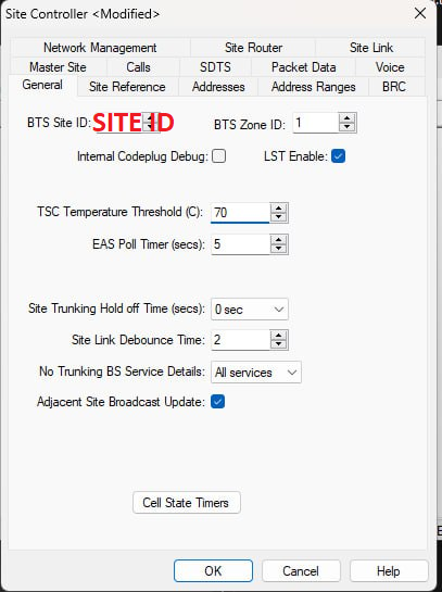
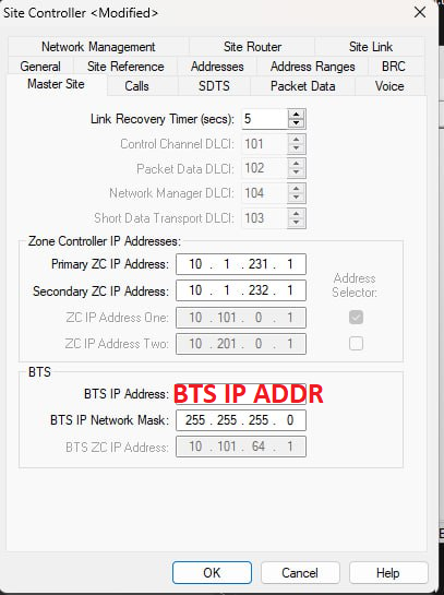
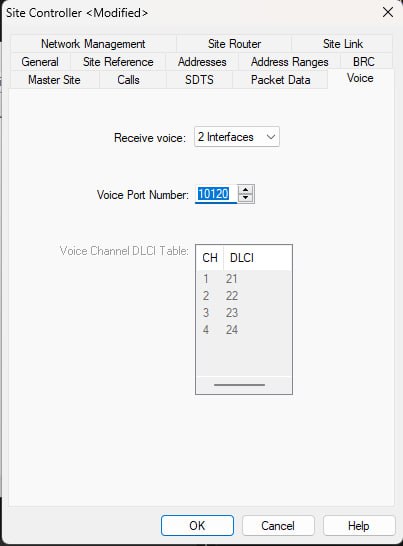
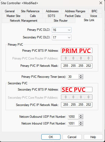
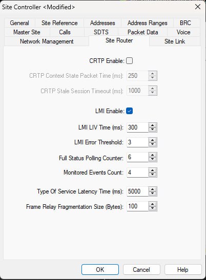
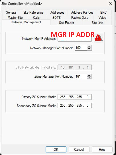
- Open the TSC Configuration file you just pulled via File ==> Open. Edit the Site Configuration via Personality ==> Modify. Click on "Edit Site Controller"
- From the Core Team, you should have received the following data: Site ID, BTS IP Address, PVC Primary, PVC Backup and Network Mgr IP Address. Make sure you have them close by, you'll need them now.
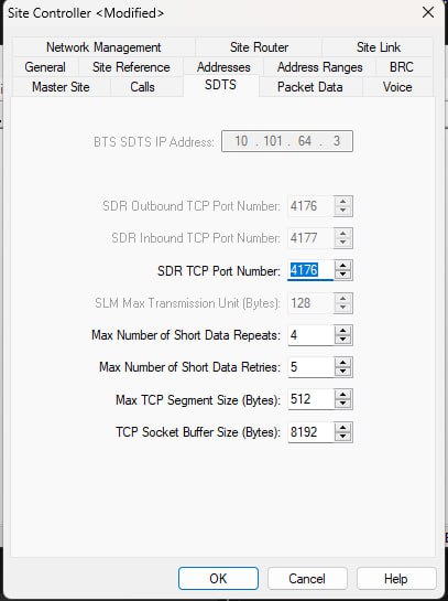
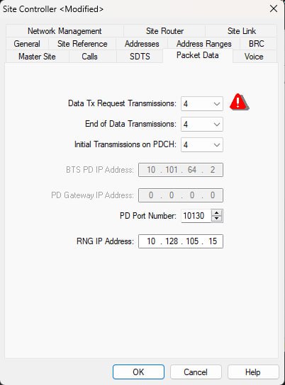
- Check your configuration matches the screenshots below, and copy over your site-specific data:


- Once you're finished, double check everything. Save the file, and reconnect to the TSC (Connection ==> Connect Direct).
- Click on Connection ==> Send Files. Select "Configuration Files" and select the file you just saved. In the “File Download” window, enter a version label, check “Use Next” and click on “Update Selected Items”. Press OK to start the transfer. You'll get a prompt to select which configuration file to replace. Select the one with all the minus signs.
- Remember when uploading the new configuration to update the "Use Next" Flag
- Reset the TSC by issuing the "reset" command on the terminal. Wait for the reboot, and log yourself in again (with factory/factory)
- Type the following commands to enable Site Link:
.sitelink -e1 .e1config -crdStart 1 -crd 31 -ts16Skip off -portNo 1 -crc on reset - After reboot, your TSC should now be connected to the Core Network! Enjoy :)
Final Steps
Once you have connected your BTS to the Core Network, Please go to https://map.tetrapack.online and register your user.
When an admin approves your user, you can log in and add your BTS to the map!
You will need the following information available when registering your BTS:
Zerotier Client ID: you will get this when setting up your Pi for Either Cisco or FRED configuration.
TX Frequency
RX Frequency
Duplex Table
Duplex Spacing
Once the BTS is approved by an Admin it will appear automatically on our BTS Map!
Cable Management Mod for Option 1
I found it quite convenient to put the Pi inside the empty Primary Network Module slot. A small mounting plate with double sided tape, another one for the USB/Eth dongle, and it's already much cleaner!
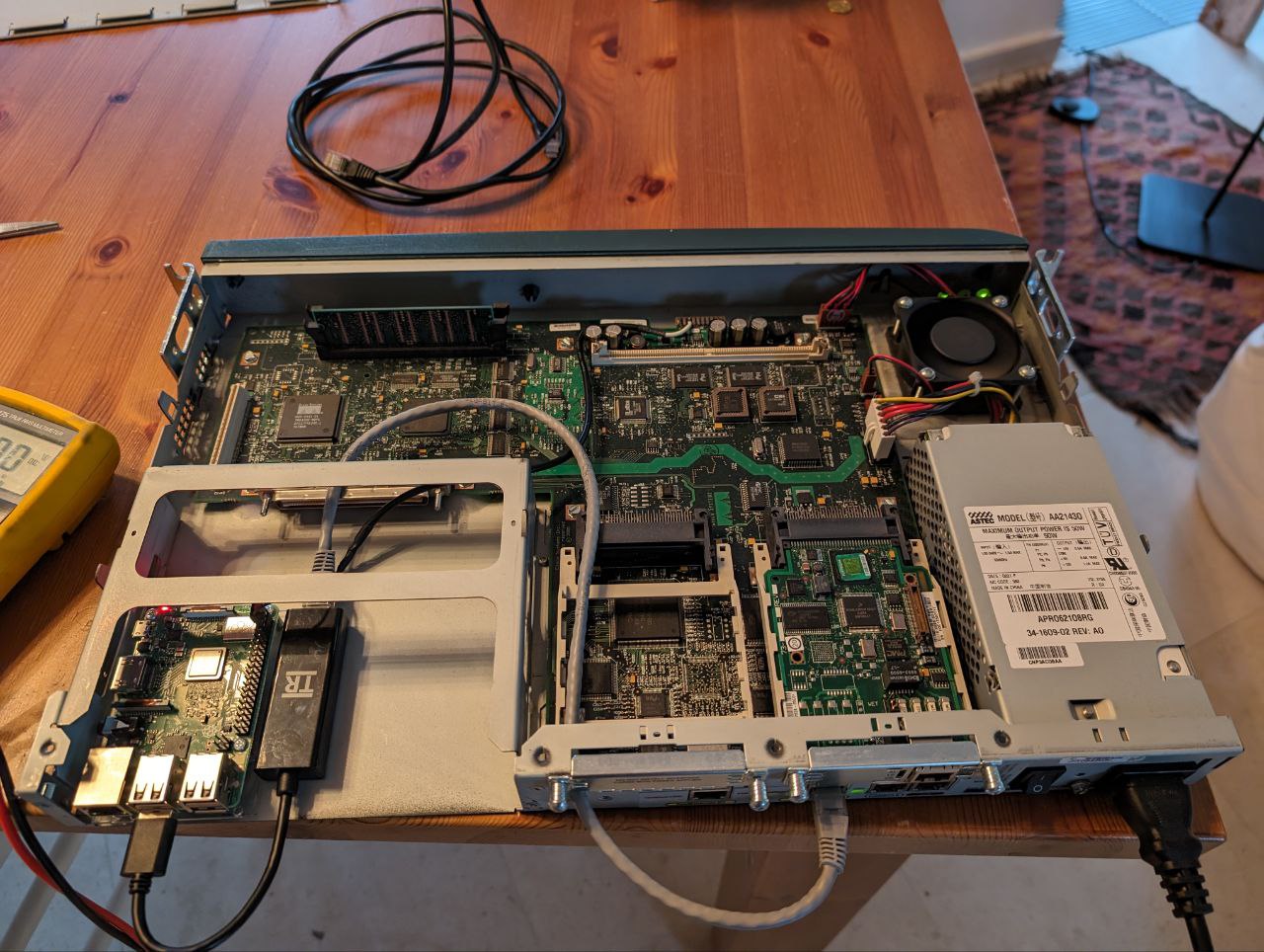
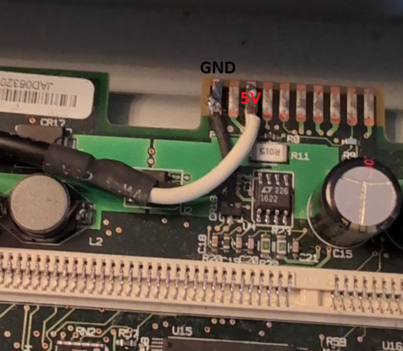
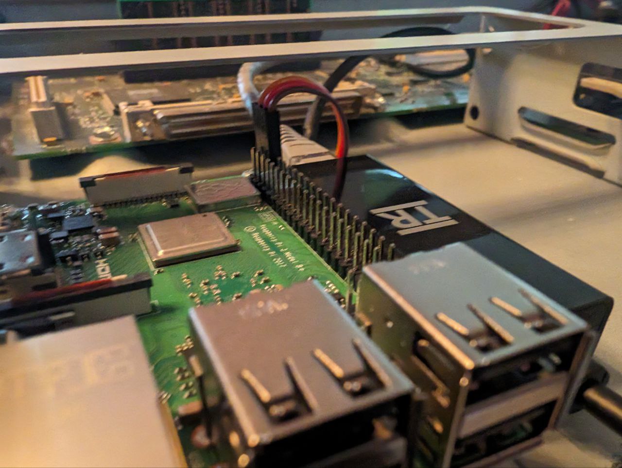
Bonus points if you use the Cisco Router's power supply to supply 5V to the Pi! Just solder a couple of wires on the edge card connector at the front of the router's mainboard. Leftmost pin is GND, then 12V (don't solder there!) then 5V. Double and triple check with a multimeter before hooking the Pi up.
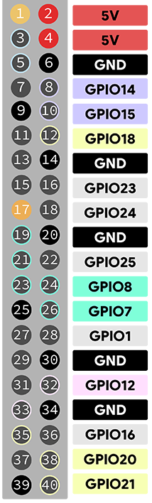
Pins 2 and 6 on the Pi can respectively be used as 5V and GND. An old servo connector does the job quite well!
Dummy
Intro
- Gateway software to run on on-site E1 connection (see article E1/T1 Interface)
- Transmits application-level messages between CTS E1 and TetraPack Core
- Decodes/encodes full signalling stack:
- E1 handler \
- HDLC FSM - (normally done by IC on BSC411 board)
- Q.921 FSM /
- Inter-site Connect transport including priority management (normally done by ISCD2.EXE)
- Decodes/encodes E1 and pre-buffer carrier streams (normally done by BSC411/TR412 boards)
- Partially emulates BSS.EXE/GWS.EXE (presence / status updates)
- VTUN over E1 between CTS and host (does not forward to the server)
- Uses the same bss3.txt configuration file as a base-station
- Has additional D-BUS API to pass specific data types such CTS logs to the server
- Debian 11 arm64 or amd64, tested on Raspberry Pi 3*, CM4 and Intel x64 PC
- Typical IP bandwith 4-100 Kbits/sec
* Some revisions of Raspberry Pi 3 have issues with icE1usb connection stability due to USB NIC
Configuration
Default configuration file is /opt/TetraPack/default.env
# E1D interface and line in format [interface number].[line number]
DUMMY_LINE=0.0
# Path to CTS topology file (bss.txt or bssparams.txt)
DUMMY_TOPOLOGY=/opt/TetraPack/bssparams.txt
# IP address and mask for CTS VTUN interface
DUMMY_NETWORK="192.168.0.8 mask 255.255.255.0"
# Specific options (multiple values can be delimited with comma):
# replace-forwarded-link-status - replace IP-forwarded status for both E1 lines status of local BSs/GWPC to up
# emulated-bs-line1-down - set E1-1 status of emulated BS to down
# emulated-bs-line2-down - set E1-2 status of emulated BS to down
# emulated-gwpc-line1-down - set E1-1 status of emulated GWPC to down
# emulated-gwpc-line2-down - set E1-2 status of emulated GWPC to down
DUMMY_OPTION=
# Server connection URI in format http(s)://[user]:[password]@[address]/[path and parameters]
# If you care about securely stored password, please put credentials into /opt/TetraPack/.netrc (man netrc)
DUMMY_CONNECTION="http://xxxxxx:password@core.tetrapack.online:8081/dummy/?emulation=bs+gwpc"
# Instance name for D-BUS IPC interface
DUMMY_INSTANCE=default
Connection URL
Parameters:
- emulation
- bs - tells Core to emulate basestation, required to deliver group and private calls. Emulated basestation will use ID from topology file (/base-station/base-station-id)
- gwpc - tells Core to emulate GWPC, required to forward SMS, location, etc. Please don't use if you have GWPC on-site
Topology
bssparams.txt is used to map CTS system topology and E1 layout as well as a system configuration. Parameter /base-station/base-station-id is used as identifier of emulated basestation (identifier of GWPC is hardcoded in CTS).
A capacity (amount of concurrent calls) of emulated basestation depends on amount on configured virtual transceivers for this basestation. Capacity = [count of transceivers] * 4 - 1
Please keep in mind that due to specific of CTS system topology must me configured as a chain of nodes, connected end-to-end. For example if you have two physical BSs, topology file has to be configured in scheme BS1 <-> BS2 <-> emulated BS <-> emulated GWPC. Regarding to this scheme you have to have properly configured termination endpoint in the main configuration (.env):
# emulated-bs-line1-down - set E1-1 status of emulated BS to down
# emulated-bs-line2-down - set E1-2 status of emulated BS to down
# emulated-gwpc-line1-down - set E1-1 status of emulated GWPC to down
# emulated-gwpc-line2-down - set E1-2 status of emulated GWPC to down
DUMMY_OPTION=emulated-gwpc-line1-downMultiple instances
You can have several separated CTS systems connected to one or more core servers (for example, production and test). For such case you need to have several .env files for each configuration. use sudo ./setup.sh install to register all instances.
Also it's possible to run dummy in command line - sudo ./run.sh <configuration.env>
CTS Log Collector
CTS Log Collector is an additional software for Dummy. It connects to CTS basestation via TCP to logging ports and forward log entries to locally installed dummy.
The need
CTS Log Collector does following important things:
- gets GSSI attachments (Scan List) information from logs and passes to the core - required to manage group routing (no such data in signalling)
- passes log to logging server to simplify analysis of issues
Configuration
# [IP of basestation] [dummy instance name] [basestation ID (1-8)]
COMMAND_ARGUMENTS=10.0.0.1 default 1
MTS
Motorola's MTS Series of Tetra Base Stations are currently supported in TetraPack.
Installation
curl http://packages.tetrapack.online/install/tools/MTS/mts-setup.sh | sudo bashCTS Updater
CTS Updater (update-cts.py) is a small script to upload and update CTS configuration or database remotely and without restart. Better to run it on the same Linux system where dummy runs.
Utility creates index data, starts specific embedded ftp server, connects to CTS and initiates update. After updating it stops.
Installation
sudo apt install python3-pip python3-pyftpdlib
sudo pip install telnetlib3Please make sure, you don't use firewall between your CTS and Linux. Also please make sure you have no ftp servers run on Linux system or use port TCP 21.
Usage
$ sudo ./update-cts.py <IP-address of CTS> [db|cfg] <path to folder>Exit codes:
- 0 - Success
- 1 - Error on Linux system
- 2 - Error on CTS system
Update database
$ ls db1/
sum-gm.csv sum-gp.csv sum-sc.csv sum-sub.csv
$ sudo ./update-cts.py 10.2.0.10 db db1 ; echo $?Update configuration
$ ls -l cfg1/
bssparams.txt
$ sudo ./update-cts.py 10.2.0.10 cfg cfg1 ; echo $?CTS
Motorola CTS-x00 is a series of basestations for CompactTETRA product line of Motorola. Literally its OEM-product of DAMM with software from Frequentis.
Following articles is about how to connect it to TetraPack:
SmartConnect
Configuration Guide
This guide explains how to configure SmartConnect on supported Motorola MXP600, MXP660 and MXM600 radios for use with TetraPack
The instructions assume the user has already purchased the "SmartConnect" feature license and has compatible firmware installed on the radio.
Requirements
Before configuring SmartConnect, ensure the following prerequisites are met.
Radio Requirements
The radio must have:
-
SmartConnect feature licensed
-
Firmware MR2025.2b or newer
-
Working Wi-Fi capability
- MS Authentication DISABLED
Software Requirements
Configuration requires:
-
Motorola Tetra CPS Plus 8.4 or newer
Network Requirements
The radio must have access to the internet via Wi-Fi and be able to reach TetraPack Core.
Endpoint
The TetraPack endpoint is:
![]()
REMEMBER - If your Hotspot Password contains Special Characters, these need to be entered into CPS URL Encoded.
For Example.
P@ssw0rd! = P%40ssw0rd%21
Radio Configuration (CPS)
Open the radio configuration in Tetra CPS Plus 8.4.
Step 1 – Configure Wi-Fi
Create a new Wi-Fi profile and configure:
-
SSID
-
Security mode
-
Password
Write the configuration to the radio.
Step 2 – Configure SmartConnect
Within CPS, configure the SmartConnect connection parameters.
Enter the TetraPack endpoint:
REMEMBER - If your Hotspot Password contains Special Characters, these need to be entered into CPS URL Encoded.
For Example.
P@ssw0rd! = P%40ssw0rd%21
Write the configuration to the radio.
Troubleshooting
If the radio fails to connect to the gateway, the most common cause is a cached certificate or invalid SmartConnect Certificate.
Reset the SmartConnect certificates using the radio Test Mode.
Enter Test Mode
On the radio keypad enter:
This opens the Test Mode menu.
Delete SmartConnect Enrollment Certificates
Delete the stored certificate.
After deleting the certificate:
-
Restart the radio
-
Reconnect to Wi-Fi
-
Attempt the SmartConnect connection again
Additional Notes
-
Radios must have a valid SmartConnect feature license installed.
-
Firmware older than MR2025.2b may not support the required connection methods.
-
Ensure outbound TCP connectivity to the gateway port is allowed.
Rohill
TetraNode
Intro
Rohill TetraNode is pure IP-based solution, for better TetraPack service implementation we decided to use proprietary InterTNX protocol instead of available TetraNode Interconnect Gateway protocol (TIGv2). By this approach we created a special agent software - TetraPack Peak, which should be run inside TetraNode' private IP network and emulates a subset of required TNX functionality. 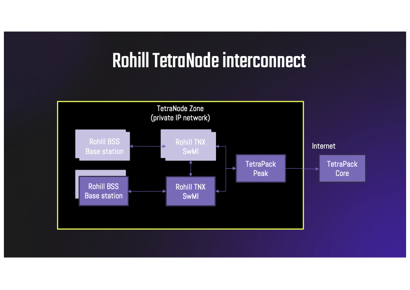
On the one side it connects to TNXs directly, on the other side it connects to TetraPack Core system over public Internet.
Limitations
- TetraPack Peak should be run inside TNX' private network
- It requires separated Debian Linux host with amd64 or arm64 architecture (could be dedicated PC, Raspberry PI or virtual machine)
- All TNX nodes inside zone have to use numeric node names from 1 to 62
- TetraPack phone trunks should have numeric names that equal to corresponding ISSIs (16777184, 16777186)
- At least TetraNode 2.28
- Good license to pass as much ISSIs as possible :)
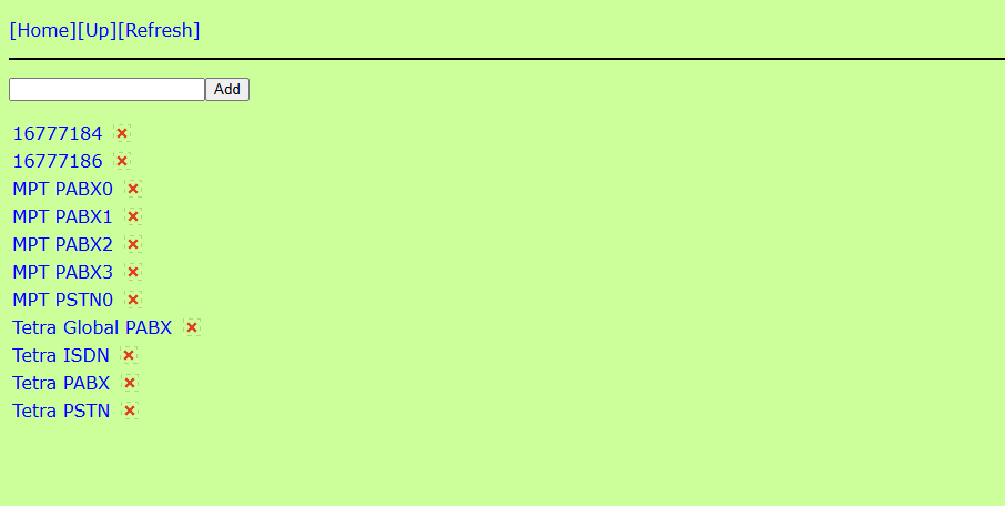
Every ISSI to be accepted by TNX from TetraPack should be added to TNX database (e.g. to make a Group Call, every ID involved in the call needs to be in TNX database)
Peak installation and configuration
- Add repository and install a package
curl http://packages.tetrapack.online/install/tools/Debian/add-repository.sh | bash sudo apt install -y tetrapack-peak - Configure Peak - /opt/TetraPack/default.env
# TNX connection settings # Port settings should correspond to values on your TNXs NODE_PORT=39451 CONFIG_PORT=39450 # That is optional multicast address used by TNXs for discovery # If you use broadcast or static configuration, you can comment it CONFIG_ADDRESS=238.1.2.3 # You have to use any free Node ID since Peak emulates a node, # exchange and location should be unique inside TetraNode zone LOCAL_NODE=3 LOCAL_EXCHANGE=peak LOCAL_LOCATION=peak # Server connection URI in format http(s)://[user]:[password]@[address]/[path and parameters] # If you care about securely stored password, please put credentials into /opt/TetraPack/.netrc (man netrc) TRANSPORT_CONNECTION="http://core.tetrapack.online:8081/peak/?country=901&network=9999" - Restart service - sudo systemctl restart peak@default
- Logs are available in syslog / journald
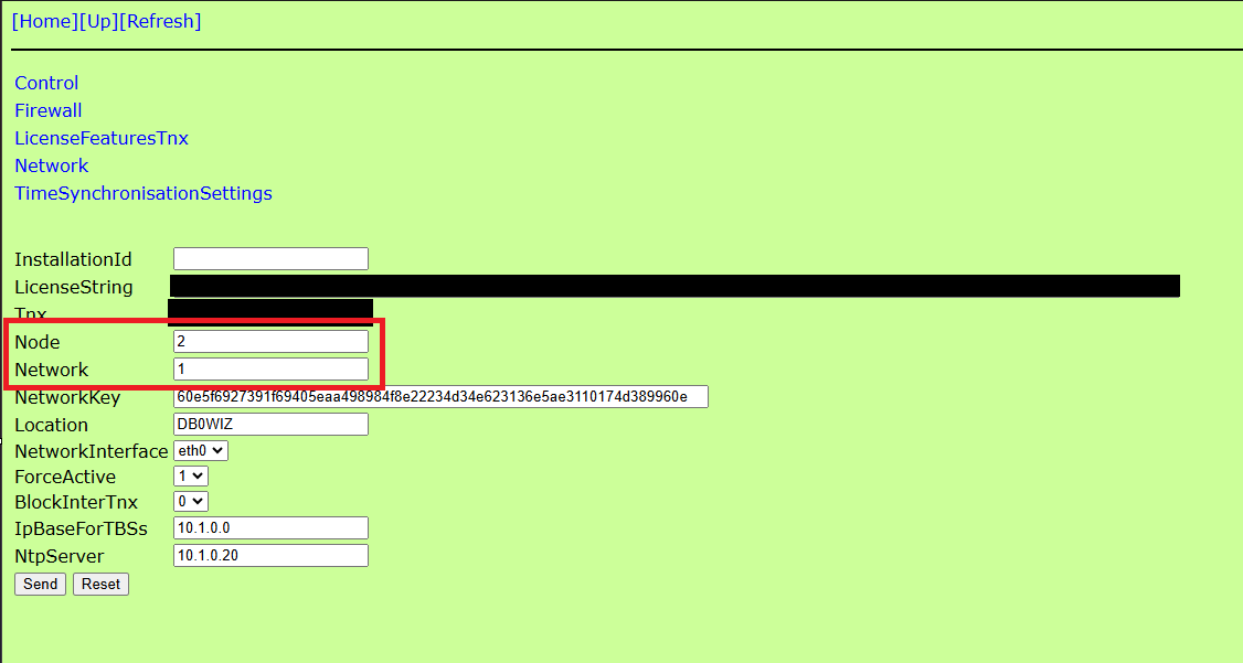
TNX configuration
Node Settings
as above All Interconnected Nodes must have Numerical ID's
Settings can be configured via WebNMS at the link http://#IP_OF_TNX#/nms/Tnx/Install
The Settings should look Similar to the Below:
InterTNX
This is usually fine to leave as the Defaults - But the main Setting to Watch out for is in the InterTNX Configuration.
this Watches on a Multicast Address (238.1.2.3 By Default)
It Can be Checked via the TNX WebNMS Configurator:
http://#IP_OF_TNX#/nms/Tnx/InterTnx
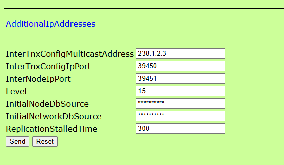
the page should look like the above (If the default configuration is still applied.
If not, Match these Settings.
Network Protocol
as of 03/01/2024 - a bug in the Network Protocols of TNX was discovered when connected to a peak instance.
in that if an ID was registered in the DMR Network, it would then not register via RF to a TetraNode.
in the event that an ID cannot register via RF after connecting to the DMR Network, please wait 10 Mins and reboot the tetra radio.
please check the following URL and ensure that "ForwardRegistration" is set to "Supported" and "LA Timer" is set to "10 Minutes"
http://#IP_OF_TNX/nms/Network/Protocol/Tetra/TetraRegistration

Telephony (PABX)
as of 2nd January 2025 TetraPack now supports telephony integration directly with Rohill TetraNode.
In order to configure this you need to check a couple of settings at "Network" level within your TNX.
1) http://#IP_OF_TNX/nms/Network/ExternalGateways inside this Page, Create 2 new External Gateways named "16777186" and "16777184"
ExternalGateways
Gateway - 16777186
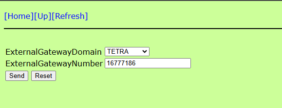
Gateway - 16777184

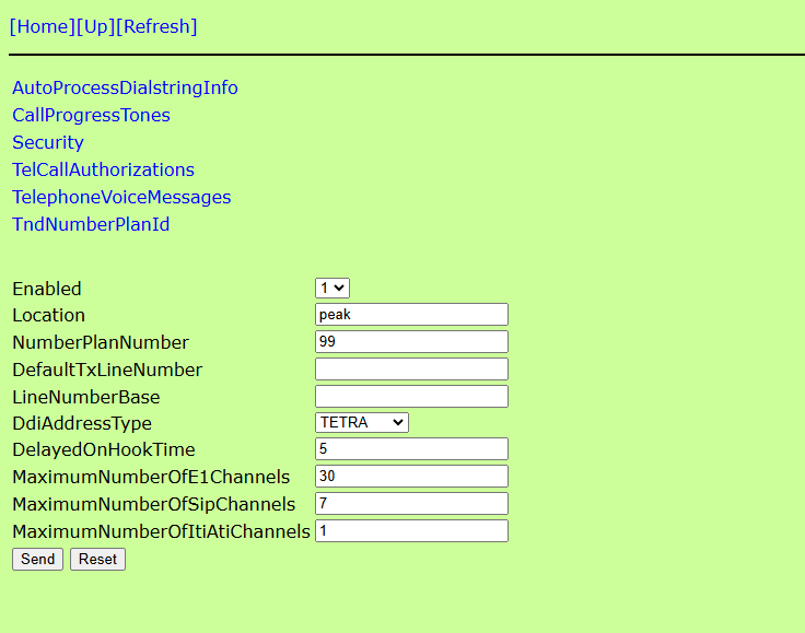
2) http://#IP_OF_TNX/nms/Network/Trunks in this section create 2x new Trunks named "16777186" and "16777184"

3) Once Created, enter the Trunks and Ensure that both of them match the settings in the Screenshot Below:
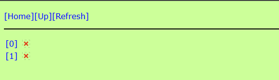
4) http://#IP_OF_TNX/nms/Network/SubscriberProfiles/Default/TrunkMapping - See Here, you will notice a single entry with the name "[0]" - From here copy and paste the below URL in order to create a second entry: http://#IP_OF_TNX/nms/Network/SubscriberProfiles/Default/TrunkMapping?add=%5b1%5d
Your Page should look like this now:
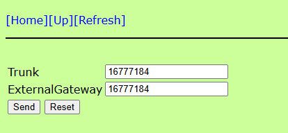
5) Configure the TrunkMapping Parameters as per the below Photographs:
Entry [0]

Entry [1]
6) Reboot your TNX and once reloaded navigate to http://#IP_OF_TNX/nms/Network/Status/TrunkLocations if everything is configured correctly you should see the 2x Following entries.
(Note - "@3" May show differently, this will be the Node ID of Peak that you configured in "LOCAL_NODE" in the configuration file)

7) Try and make a PABX call from your Radio (You can access the TetraPack Core Echotest program at Number 600 as a PABX Call)
Hytera
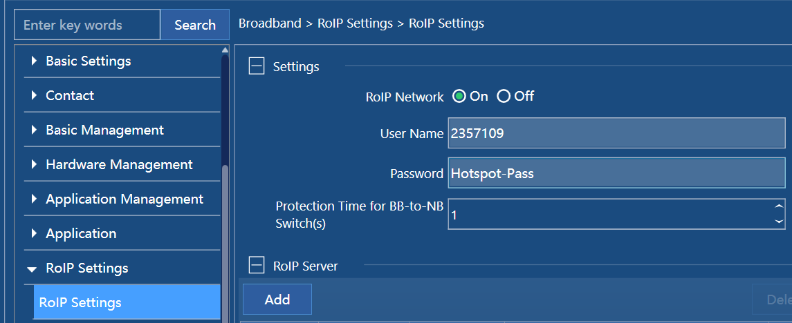
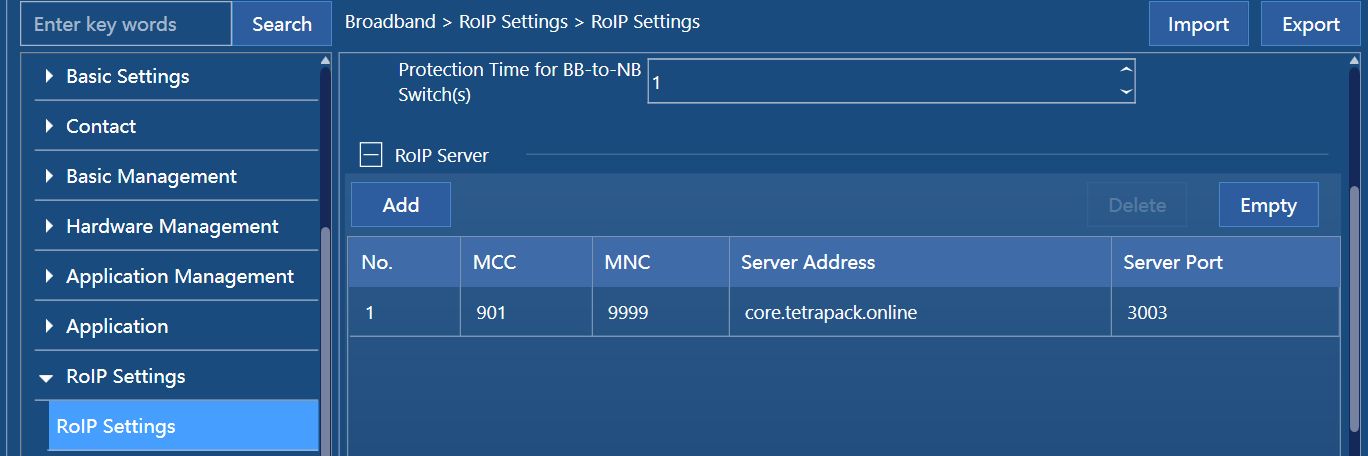
Hytera RoIP
- User name - your ID
- Password - your BM’s hotspot password

- MNI - set what do you use in TMO configuration, most probably its 901 9999
- Server - core.tetrapack.online (domain name, not IP! that's strict)
- Port - use standard 3003

PTC760 and PTC680
TETRA
- It works on EBTS as well as on CTS.
- Group calls, individual calls (duplex and simplex), scan-lists work well. Phone calls require to switch radio to full-duplex mode first (how they are going to make phone calls in half-duplex? ;)).
- PD and SDS don’t work at all. Since I have tested it on EBTS and CTS, it’s FW bug (3.5, from the factory). I was checking with adb and it seems there is a kind of mismatch between NB and Android parts of device. At least in case of PD phase of PDP attach finishes well, CHAP works correctly, the problem comes on the latest part of attach on the radio.
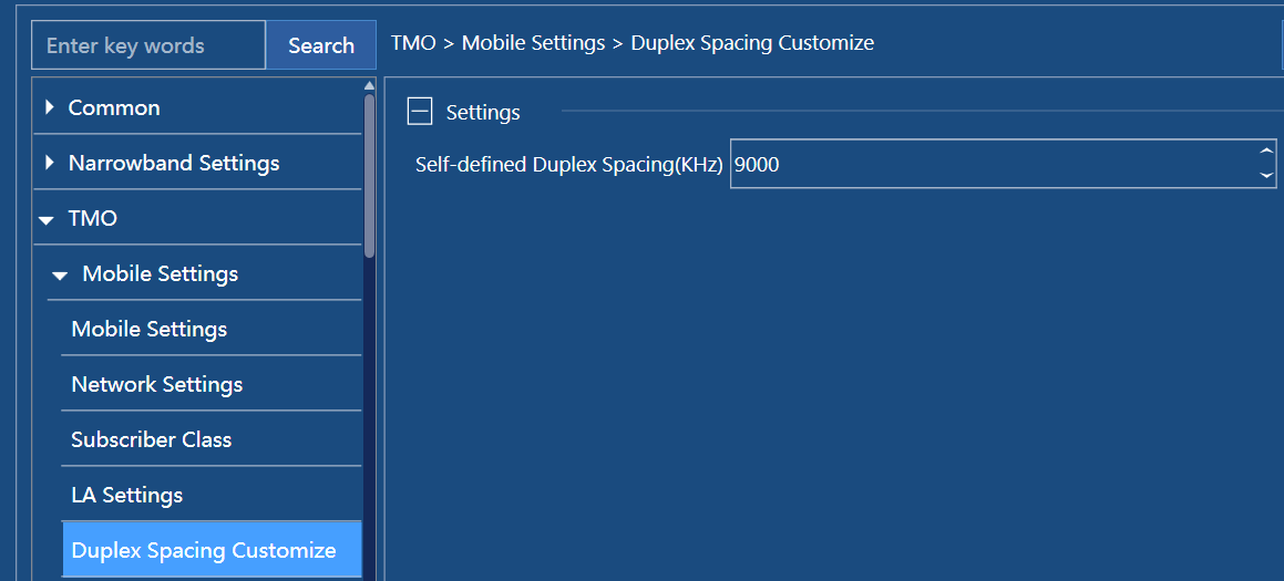
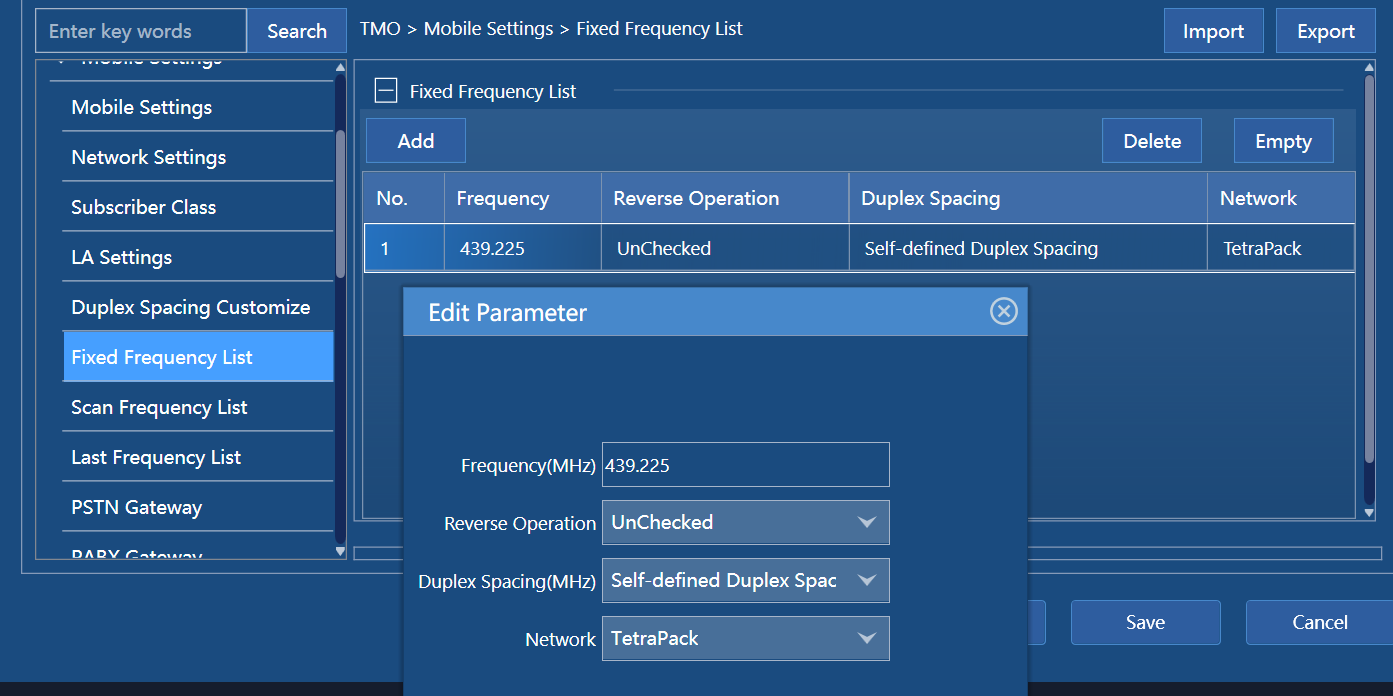
- It has some specific with spacing configuration. Standard spacings 0-4 are hardcoded in FW. User-defined spacing uses index 7.


So if your EBTS/MBTS/MTS uses 7.6 spacing at index 7 there is no problem. But in case of CTS there is a difficult. CTS allows only to configure spacing to indexes 0-4 or so. So since i use CTS as a „hotspot“ with dummy load I decided to switch spacing to index 3 and 8 MHz by moving lower frequency down a bit. Most of CTSs use index 1 with 7.6 to fit to allocation with keeping limitations in mind.
RoIP
Tested on A7 3.5 and A10 4.5 firmwares.
- User name - your ID
- Password - your BM’s hotspot password
- MNI - set what do you use in TMO configuration, most probably its 901 9999
- Server - core.tetrapack.online (domain name, not IP! that's strict)
- Port - use standard 3003
Location / APRS
APRS location information is accepted from the PTC760 via RoIP and RF, configured in the same way as the Dimetra APRS Settings.
The PTC760 also allows you to specify a LIP Location for both TMO/RoIP and DMO separately, meaning your APRS should work between TetraPack and the HAM-TETRA networks seamlessly.
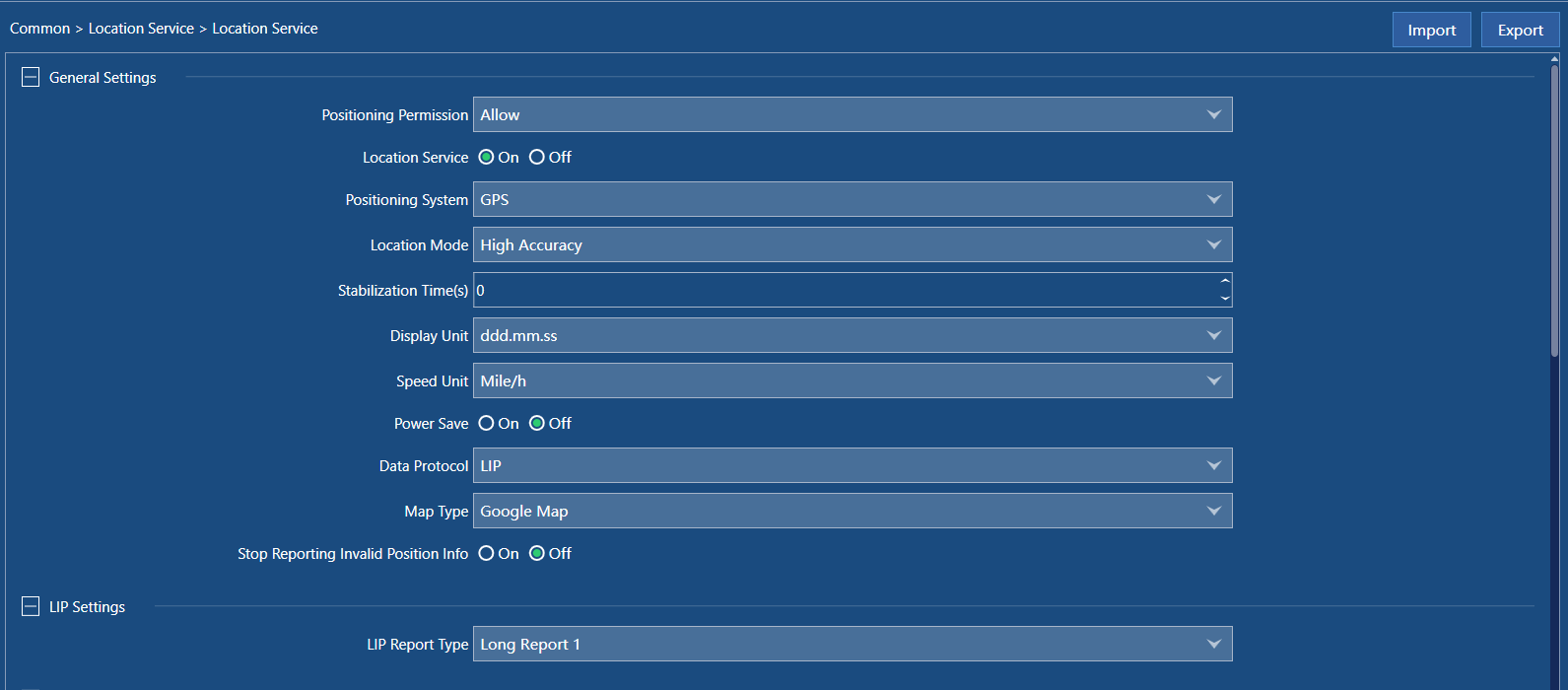
General Location Service Settings
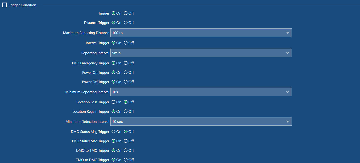
Example Triggers
Control Centers (Destinations)
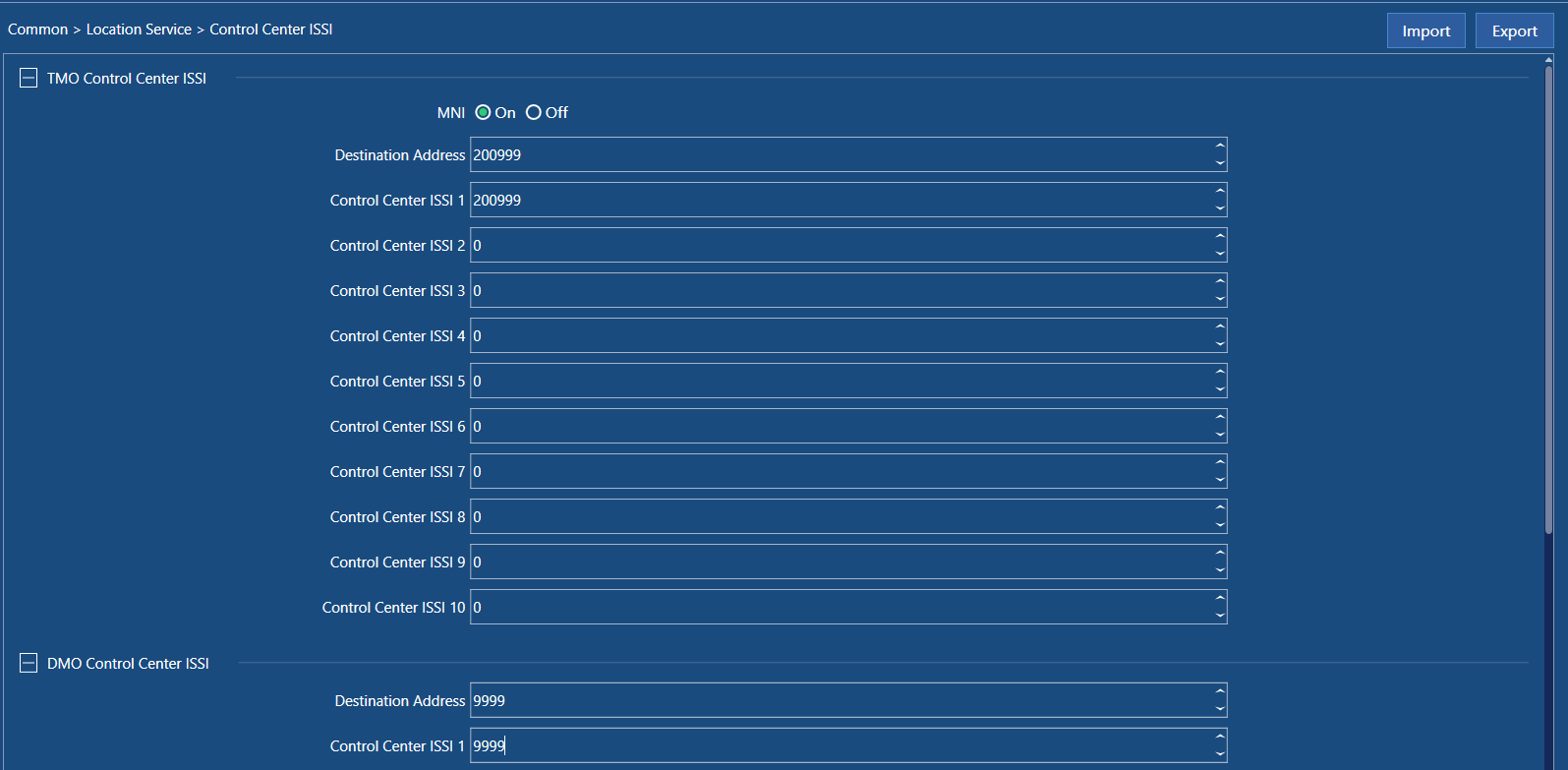
Remember that on TetraPack there is only 1x destination for Location Data, 200999
What you have to know else:
We have call floor management but without late call entry. So when call will be preempted or overlapped the next one will come only when the it begins. Only Scan List are affected with this specific. In general the late call entry is supported by TetraPack inside each GSSI.
Scan lists and SDSs are supported.
Interfacing
E1/T1 Interface
Why not TDMoIP / CESoIP?
Usual E1/T1 over IP protocols use generic frames over IP transfer that makes more than 2 megabits constant rate with up to 8000 packets per second. That approach:
- not suitable for distributed sites with limited internet access
- makes constant parasite load on the servers
- requires delays to compensate jitters
- has issues with asynchronous-to-synchronous transition
Fur such kind of integrations we prefer to have our own agent software on-site with hardware E1/T1 interfaces.
- good timings driven by E1/T1 clock or GPS
- good framing due to synchronous composition on the site
- less traffic due to transfer only valuable demultiplexed information
icE1usb
We have chosen Osmocom icE1usb as a primary interface for our projects for several reasons:
- good compatibility with big range of hardware hosts due to use of USB
- in opposite to most of DAHDI interfaces it is in production
- open-source hardware design
- open-source user-space driver, no need for the kernel driver
- suitable API for our purposes (at least full-frame mode)
- available at Sysmocom's web shop
User manual can be found here.
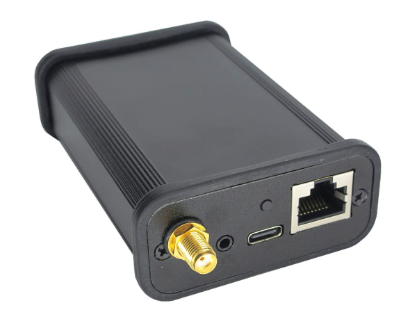
NOTICE
Please be careful! Or your device will be damaged! Front-panel RJ45 connectors accepts 120 Om E1. Back-panel RJ45 is for GPIO and accepts TTL only. Don't try to connect the device to Ethernet. USB-C port should be connected to computer, since it's just an interface. Minijack connector is only to reprogram firmware. Also please configure properly internal jumpers to master (NE) or slave (NT) E1 mode.
PLEASE READ USER MANUAL FIRST.
Hardware configuration
Almost in all our cases you need this interface in NT (Network Termination) mode. In this mode the interface works as a network side and you can use a normal Ethernet cable for connection (no crossing required).
To change the mode, unscrew the 2 PH0 screws on the side with the 2 RJ45 jacks. You’ll also need to unscrew the nut on the SMA jack on the other side. After that, the cover plate and rubber gasket around the 2 RJ45 jacks can be removed. The PCB can be slid out of the case.
Then swap the jumpers so they match this picture:

Driver installation
You can get Osmocom E1D from Osmocom's Debian repository (amd64, arm64).
sudo apt install extrepo
sudo extrepo enable osmocom-latest
sudo apt update
sudo apt install -y osmo-e1dDriver configuration
/etc/osmocom/osmo-e1d.cfg
log syslog daemon
logging level force-all fatal
e1d
interface 0 icE1usb
usb-serial [interface serial number]
line 0
line 1More information about logging section can be found here, here and here.
(If you care about configuration file format, please check the sources here).
How to find a serial number of connected icE1usb:
sudo lsusb -d 1d50:6145 -v 2> /dev/null | grep iSerialReload a service:
sudo systemctl restart osmo-e1dYou can also test your configuration from the command line:
sudo osmo-e1d -c /etc/osmocom/osmo-e1d.cfgRecomended settings
/etc/rsyslog.d/99-e1d.conf
if ($programname contains "osmo-e1d") and (($msg contains "Received Only 0 bytes") or ($msg contains "TS read underflow")) then {
~/dev/null
stop
}/etc/systemd/system/osmo-e1d.service.d/override.conf
[Service]
TimeoutStopSec=2s
Issues with the second E1 port
Please note that on many XHCI host controllers there seem to be implementation flaws in the XHCI host controller firmware preventing the activation of both icE1usb ports simultaneously. The XHCI controller firmware erroneously claims that there is insufficient bus bandwidth. However, the same icE1usb hardware/firmware works perfectly fine with OHCI, UHCI and EHCI host controllers. See https://osmocom.org/projects/e1-t1-adapter/wiki/Isochronous_USB_Issues for a user-maintained list of USB hosts / controllers and whether or not they work with two E1 ports.
In most installations it's not a real issue, because of need in a single port only.
We have tested it with following equipment:
- Raspberry Pi 3, 4, CM4 - only first E1 port is working
- Raspberry Pi 5 - both E1 ports are working when connected to blue USB port
FrameRelay over E1
FrameRelay-over-E1 Daemon (FRED)
Intro
- Gateway software to run on on-site E1 connection (see article E1/T1 Interface)
- Bridges IPv4/IPv6/Ethernet packets between Linux kernel and FrameRelay over E1 (RFC 2427, RFC 2590)
- Suitable to connect Motorola EBTS (can be used instead of Cisco routers with E1 card installed)
- Supports FRF.12 (inner and outer) fragmentation for incoming traffic (Frame Relay -> Linux)
- Implements basic DCE-PVC LMI with support of ITU-T Q.933-A, ANSI T1.617-D, GOF (automatic detection)
- Acts via TUN/TAP network interfaces (one per DLCI) on Linux side
- Debian 12 arm64 or amd64, tested on Raspberry Pi CM4, Raspberry Pi 5
Installation
sudo apt install extrepo
sudo extrepo enable osmocom-latest
curl http://packages.tetrapack.online/install/tools/Debian/add-repository.sh | bash
sudo apt install -y osmo-e1d fredConfiguration
Default configuration file is /opt/FRED/default.env
#
# Parameters for FRED binary
#
# E1D interface and line in format <interface number>.<line number>
FRED_LINE=0.0
# E1 slot list in format <first slot>-<last slot>
FRED_SLOT_LIST=1-31
# FrameRelay feature list in format <option>[,...]
# FRF.12-OUTER - outer frame sequence counting and fragmentation (incoming frames only supported)
FRED_FEATURE_LIST=
# DLCI list in format <DLCI>:<type>[,...]
# LMI-DCE-PVC
# IP - IP bridge (RFC 2427 for IPv4, RFC 2590 for IPv6)
# ETH - Ethernet bridge (RFC 2427)
FRED_DLCI_LIST=0:LMI-DCE-PVC,16:IP,17:IP
# Path to configuration script to manage IP interface configuration on up and down
FRED_SCRIPT=./dimetra-hook.sh
#
# Parameters for dimetra-hook.sh
#
# Zone ID
DIMETRA_ZONE=1
# Local Site ID
DIMETRA_SITE=12
# FrameRelay DLCIs
DIMETRA_DLCI_PRIMARY=16
DIMETRA_DLCI_SECONDARY=17
# When set, routes will be added to FRR's OSPF prefix list
FRR_PREFIX_LIST=dimetra
Use with Dimetra
FRED package includes prepared scripts to establish connection between EBTS and Dimetra MPVPN network.
sudo /opt/FRED/dimetra-setup.shBest settings for EBTS TSC will be:
.sitelink -e1
.e1config -crdStart 1 -crd 31 -ts16Skip off -portNo 1 -crc on
resetMultiple instances
You can have several separated systems connected to a local Linux system. For such case you need to have several .env files for each configuration. use sudo ./setup.sh install to register all instances.
Also it's possible to run FRED in command line - sudo ./run.sh <configuration.env>
Radio Settings
Articles in other sections:
Generic settings for TetraPack
Specific setting for bridged individual calls
It's recommended to use these settings on the TETRA radio to have better user experience on TETRA side
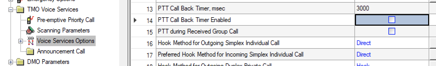
- PTT Call Back Timer - Disabled
(respond for initial delay on call DMR->TETRA) - Hook Method for Outgoing Simplex Individual Call - Direct
(respond only for transmitted call properties, the bridge is tolerant to this setting) - Preferred Hook Method for Incoming Simplex Individual Call - Direct
(allows TETRA radio to hook a call automatically - DMR side doesn't know about when the call hooked)
Specific setting for bridged group calls
It's recommended to use these settings on the TETRA radio to have better user experience on TETRA side
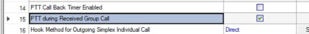
- PTT during Received Group Call - Enabled
(allows to transmit to group without waiting, suitable for busy groups)
Location reporting
Core supports LIP and NMEA reports over SDS. Typical ISSI is 200999 (same as in DMR), where xxx is a MCC of connected core.
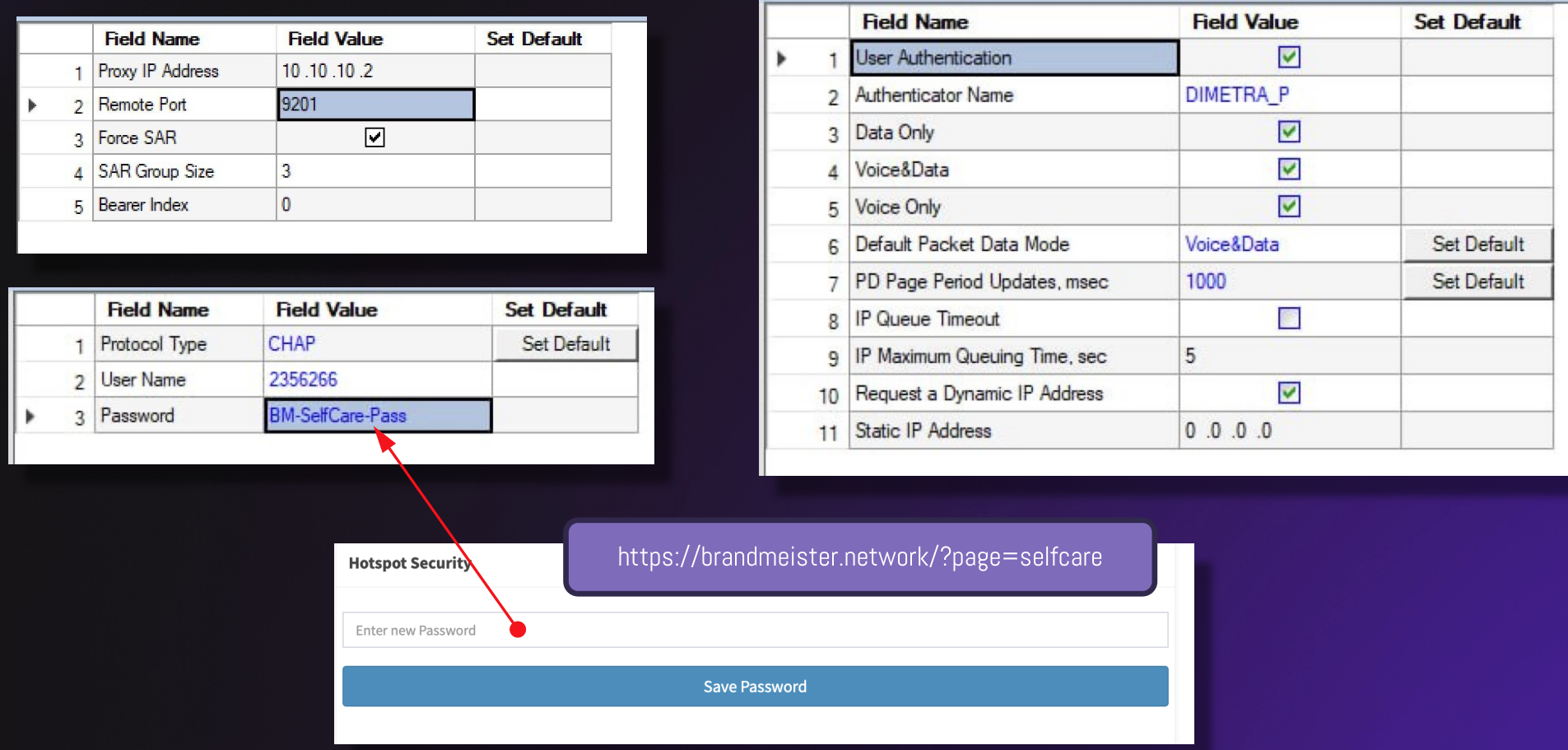
Settings for Mobile IP-data and WAP
Some points, if you get access via Dimetra-based system:
- Password authentication using CHAP
- Password can be set in BrandMeister’s dashboard (hotspot/repeater password)
- Should be enabled per ISSI by administrators (please ask for it in Tetrapack support group https://t.me/TetraPackGeneralSupport )
For Motorola radios you should have these settings in CPS:
Server Bridging
Asterisk PBX
Disclaimer
-
TransitBridge is only available on the same host as TetraPack Core, so the target of this document is a server administrator. Other Asterisk systems can be connected to transit Asterisk system via IAX2, SIP, etc.
-
TransitBridge (as well as DetroitBridge) is plug-and-play, no extra configuration required.
-
TransitBridge channel driver uses only default dialplan context. Please use GotoIf or Lua.
-
Some TETRA Systems (at least CTS) don't support external numbers (PSTN on PABX) for messaging.
-
Some TETRA Systems (at least CTS) don't support PABX calls (PSTN or ISSI only).
Modules
- codec_pack.so - TETRA codec definitions and translations, uses our own library CodecPack.so
- chan_transit.so - TransitBridge channel driver
Environment variables
CODECPACK=/<path>/CodecPack.soasterisk.conf
[options]
systemname = <numeric ID of local system>Dialplan
Outbound calls
Dial(Transit/<Core ID>/<ISSI>[/<options>])Where options are:
- s - Use simplex call with PTT control (RADIO_KEY/RADIO_UNKEY, see app_rpt)
- t - Use PSTN call (source ISSI 16777184, CALERID(num) is passed as an external number)
- b - Use PBX call (source ISSI 16777186, CALERID(num) is passed as an external number)
- n<ISSI> - Use specified source ISSI and pass CALLERID(num) as an external number
- c<0-3> - Use service number 0-3 (at this moment only 0 / ACELP is supported)
- p<0-15> - Set call priority
By-default duplex individual call with ACELP (0) and normal priority (0) will be created.
Example:
Dial(Transit/2505/${EXTEN}/t)Inbound calls
Channel variables:
- TRANSIT_TYPE=ISSI - Extension ID contains destination ISSI
- TRANSIT_TYPE=Number - Extension ID contains destination external number
- TRANSIT_FLOW=PTT - Simplex call
- TRANSIT_ISSI=<ISSI> - Destination ISSI
(only when TRANSIT_TYPE=Number, should contain 16777184 for PTSN call or 16777186 for PBX call) - TRANSIT_PRIORITY=<0-15> - Call priority
Outbound messages
MessageSend(Transit:<Link ID>[/<Destination ISSI>][,<Source ISSI>[ <External Number>]])Please keep your eyes on formatting. There no spaces in <to> section, no space after comma in <from> section and only single space between source ISSI and external number.
Channel variables:
- MESSAGE(to)=<ISSI>
- MESSAGE(from)=<ISSI>
- MESSAGE(body)=<Text>
- MESSAGE_SEND_STATUS - Will be set to SUCCESS, when the message accepted by the basestation (TNSDS-REPORT result=0), timeout is 500 milliseconds.
Asterisk API said, it corresponds to message enqueuing, not delivery, but we have a bit more. :)
Inbound messages
Channel variables:
- MESSAGE(to)=<ISSI/External Number>
- MESSAGE(from)=<ISSI>
- MESSAGE(body)=<Text>
- MESSAGE_DATA(TRANSIT_TYPE)=ISSI - Extension ID and MESSAGE(to) contain destination ISSI
- MESSAGE_DATA(TRANSIT_TYPE)=Number - Extension ID and MESSAGE(to) contain destination external number
- MESSAGE_DATA(TRANSIT_ISSI)=<ISSI> - Destination ISSI
(only when MESSAGE_DATA(TRANSIT_TYPE)=Number, should contain 16777184 for PTSN call or 16777186 for PBX)
TransitBridge sends delivery report when terminal requested that. Delivery status depends on the status of dialplan proceeding.
Technical Information
Channel ID format
Transit/<Link ID>:<Session UUID>- Link ID - decimal TetraPack Core instance identifier
- Session UUID - global call session UUID, used in TetraPack Core and BrandMeister Core (in lower case)
Specific Hangup-Cause codes
Transit <TETRA disconnect-cause code>Get TETRA disconnect-cause codes at Table 14.55 in ETSI EN 300 392-2 V3.8.1. Read more about Hangup Cause here.
Dialplan example
exten => 9XXXXXXX,1,Dial(Transit/2505/${EXTEN:1}/t)
same => n,NoOp(Disconnect Cause: ${HANGUPCAUSE(${HANGUPCAUSE_KEYS()},tech)})
same => n,HangUp()
exten => 16777184,1,NoOp(Incoming message)
same => n,NoOp(From: ${MESSAGE(from)})
same => n,NoOp(To: ${MESSAGE(to)})
same => n,NoOp(Body: ${MESSAGE(body)})
same => n,NoOp(TRANSIT_TYPE: ${MESSAGE_DATA(TRANSIT_TYPE)})
same => n,MessageSend(Transit:2505/${MESSAGE(from)},16777184 911)
same => n,NoOp(Message send status: ${MESSAGE_SEND_STATUS})SVXLink
SVXLink sources
- https://github.com/dl1hrc/svxlink/tree/tetra-contrib/ - Custom version that passes ISSIs through SVXReflector, it also has our patches applied to SVXReflector and ReflectorLogic.
- https://github.com/sm0svx/svxlink/ - Original version
Note for owners of SVXLink nodes running TetraLogic
-
Please use latest version of SVXLink software.
-
Please use the same CALLSIGN in [ReflectorLogic] and [TetraLogic] to make our bridges pass talker ISSI correctly.
Note for owners of SVXReflector servers for TETRA
-
Please use latest version of SVXReflector (at least 16082023) software.
-
Reflector to Reflector links does not pass originating ISSI.
Administrating SVXLink bridges
Disclaimer about information bellow
-
DockStation is only available on the same host as TetraPack Core, so the target of following information in this article is a server administrator.
-
DockLogic is an external Logic module is supplied outside SVXLInk.
Modules
- DockLogic.so - SVXLink Logic module that implements our own Dock IPC protocol, uses our own library CodecPack.so
- DockLogic.tcl - Supplementary script, required by SVXLink
Environment variables
CODECPACK=/<path>/CodecPack.so
svxlink.conf
[GLOBAL]
MODULE_PATH=/opt/SVXLink/lib/svxlink
CFG_DIR=/opt/SVXLink/etc/svxlink/svxlink.d
LOGICS=DockLogic,ReflectorLogic
LINKS=Link
TIMESTAMP_FORMAT="%c"
# Should be always 8 KHz!
CARD_SAMPLE_RATE=8000
[DockLogic]
TYPE=Dock
RX=Rx1
TX=Tx1
CALLSIGN=<Node call, should be completely the same as ReflectorLogic has>
EVENT_HANDLER=/opt/SVXLink/share/svxlink/events.tcl
# TetraPack Core IPC socket path
SOCKET=/tmp/Dock-<TetraPack Core ID>
# GSSI at TetraPack Core
GSSI=<GSSI of talk group at TetraPack>
# Default ISSI (used when ISSI is unknown)
ISSI=9999
# MNI for Qso:info messages (4 digits for MCC and 5 digits for MNC)
MNI=090116383
[Rx1]
TYPE=Dock
[Tx1]
TYPE=Dock
# Delay (in 60 ms frames) in bridged call start (SVXLink -> TetraPack), required for ISSI detection heuristics
DELAY=5
# Gain before encoding to ACELP (0.1 .. 1.0, default is 0.5)
GAIN=0.5
[ReflectorLogic]
TYPE=Reflector
HOSTS=<SVXReflector's DNS/IP address>
CALLSIGN="<Node call>"
AUTH_KEY="<Key>"
UDP_HEARTBEAT_INTERVAL=5
DEFAULT_TG=<Bridged SVXReflector's TG>
MONITOR_TGS=<Bridged SVXReflector's TG>
EVENT_HANDLER=/opt/SVXLink/share/svxlink/events.tcl
MUTE_FIRST_TX_LOC=0
MUTE_FIRST_TX_REM=0
[Link]
CONNECT_LOGICS=DockLogic,ReflectorLogic
DEFAULT_ACTIVE=1
TIMEOUT=0
Compatibility Chart
Disclaimer: this chart is only about type of services passed between particular systems and TetraPack Core.
For example, location services could work locally inside a system but not handled by TetraPack.
| Group calls |
Simplex individual calls |
Duplex individual calls |
Phone calls |
Text messaging |
Location | Packet data | |
| + | + | + | + | + | + | + | |
| + | + | + | + | + | + | + | |
| Hytera RoIP | + | + | + | - | + | + | - |
| Rohill TetraNode | + | + | + | + | + | + | - |
Legend:
- "+" - supported
- "-" - unsupported
- " " - unknown state
Specifications
Brew
Brew
TETRA Homebrew Protocol
Protocol is based on WebSocket version 13 (RFC 6455) without extensions. It's highly recommended to use socket options TCP_NODELAY and TCP_QUICKACK.
Endpoint, authentication
To establish a new connection client should make a HTTP GET call to get web socket's endpoint and pass authentication procedure. Authentication is based on HTTP Digest Access Authentication (RFC 2831). As a result of successful authentication server returns HTTP 200 and a URI to an endpoint to be used for WebSocket connection.
GET /brew/ HTTP/1.1
User-Agent: software-name/software-version
HTTP/1.1 200 OK
/brew/722e2b04-07ad-4976-ac55-75e845ae4d8a
Server supports following response codes: 101 (Switching protocols), 200 (OK), 301 (Moved), 401 (Unauthorized), 403 (Forbidden), 404 (Not found), 426 (Upgrade required), 429 (Too many requests), 500 (Internal server error).
HTTP header 'User-Agent' is mandatory!
WebSocket transport layer
Client should support following frame opcodes:
- Close, ping, pong. Ping and pong messages might contain a payload to measure delays.
- Single-frame masked and unmasked binary messages. Server always send unmasked messages, client may send masked messages.
Binary messages
Every message contains two-byte prefix:
- Message class
- Message type
All following data has non-aligned values in Little-Endian order
Subscriber control (mobility and affiliation, message class 0xf0)
#define BREW_SUBSCRIBER_DEREGISTER 0
#define BREW_SUBSCRIBER_REGISTER 1
#define BREW_SUBSCRIBER_REREGISTER 2
#define BREW_SUBSCRIBER_AFFILIATE 8
#define BREW_SUBSCRIBER_DEAFFILIATE 9
struct BrewSubscriberData
{
uint8_t kind; // 0xf0
uint8_t type; // BREW_SUBSCRIBER_*
uint32_t number; // ISSI
uint64_t time; // UNIX timestamp
uint32_t fraction; // Nanoseconds
uint32_t groups[0]; // GSSIs (BREW_SUBSCRIBER_AFFILIATE / BREW_SUBSCRIBER_DEAFFILIATE)
} __attribute__((packed));
TBD
Call control (message class 0xf1)
#define CALL_STATE_GROUP_TX 2 // | Simplified
#define CALL_STATE_GROUP_IDLE 3 // | Group Call
#define CALL_STATE_SETUP_REQUEST 4 // | | Origin -> Receiver
#define CALL_STATE_SETUP_ACCEPT 5 // | | Origin <- Receiver
#define CALL_STATE_SETUP_REJECT 6 // | General | Origin <- Receiver
#define CALL_STATE_CALL_ALERT 7 // | Circuit Call | Origin <- Receiver
#define CALL_STATE_CONNECT_REQUEST 8 // | | Origin <- Receiver
#define CALL_STATE_CONNECT_CONFIRM 9 // | | Origin -> Receiver
#define CALL_STATE_CALL_RELEASE 10 // | |
#define CALL_STATE_SHORT_TRANSFER 11 //
#define CALL_STATE_SIMPLEX_GRANTED 12 // | Simplex Call
#define CALL_STATE_SIMPLEX_IDLE 13 // | (on top of Circuit Call)
#define CALL_STATE_PDP_REQUEST 14 // |
#define CALL_STATE_PDP_ACCEPT 15 // | Packed Data
#define CALL_STATE_PDP_REJECT 16 // |
#define CALL_STATE_PDP_RELEASE 17 // |
#define PDP_FLAG_IPV4 (1 << 0)
#define PDP_FLAG_IPV6 (1 << 1)
struct BrewCircularCall
{
uint32_t source;
uint32_t destination;
char number[32]; // External number (ASCII)
uint8_t priority; // Call priority
uint8_t service; // Table 14.79: Speech service
uint8_t mode; // Table 14.52: Circuit mode type
uint8_t duplex; // Duplex flag
uint8_t method; // Table 14.62: Hook method
uint8_t communication; // Table 14.54: Communication type
uint8_t grant; // Table 14.80: Transmission grant
uint8_t permission; // Table 14.81: Transmission request permission
uint8_t timeout; // Table 14.50: Call time-out
uint8_t ownership; // Table 14.38: Call ownership
uint8_t queued; // Table 14.48: Call queued
} __attribute__((packed));
struct BrewCircularGrant
{
uint8_t grant; // Table 14.80: Transmission grant
uint8_t permission; // Table 14.81: Transmission request permission
} __attribute__((packed));
struct BrewGroupTransmission
{
uint32_t source;
uint32_t destination;
uint8_t priority; // Call priority
uint8_t access; // Access priority
uint16_t service; // Table 14.79: Speech service
} __attribute__((packed));
struct BrewShortData
{
uint32_t source;
uint32_t destination;
char number[32]; // External number (ASCII)
} __attribute__((packed));
struct BrewPacketRequest
{
uint32_t number; // ISSI
uint8_t flags; // PDP_FLAG_*
uint32_t profile; // GSM 04.08 QoS Profile
uint8_t authenticator[0]; // CHAP Challenge + CHAP Response
} __attribute__((packed));
struct BrewPacketContext
{
uint8_t flags; // PDP_FLAG_*
in_addr_t v4; // IPv4
struct in6_addr v6; // IPv6
uint32_t profile; // GSM 04.08 QoS Profile
} __attribute__((packed));
struct BrewCallControlData
{
uint8_t kind; // 0xf1
uint8_t type; // CALL_STATE_*
uuid_t identifier; // Call session UUID
union
{
uint8_t cause; // Table 14.55: Disconnect cause / GTP cause (ETSI TS 29.060 v3.9.0 7.7)
struct BrewShortData data;
struct BrewCircularGrant grant;
struct BrewCircularCall circular;
struct BrewGroupTransmission group;
struct BrewPacketRequest request;
struct BrewPacketContext context;
};
} __attribute__((packed));
CALL_STATE_GROUP_TX
Length and contents: offsetof(struct BrewCallControlData, data) + sizeof(struct BrewGroupTransmission)
CALL_STATE_GROUP_IDLE, CALL_STATE_SETUP_REJECT, CALL_STATE_CALL_RELEASE
Length and contents: offsetof(struct BrewCallControlData, data) + sizeof(uint8_t)
CALL_STATE_SETUP_ACCEPT, CALL_STATE_CALL_ALERT
Length and contents: offsetof(struct BrewCallControlData, data)
CALL_STATE_SETUP_REQUEST, CALL_STATE_CONNECT_REQUEST
Length and contents: offsetof(struct BrewCallControlData, data) + sizeof(struct BrewCircularCall)
CALL_STATE_CONNECT_CONFIRM, CALL_STATE_SIMPLEX_GRANTED, CALL_STATE_SIMPLEX_IDLE
Length and contents: offsetof(struct BrewCallControlData, data) + sizeof(struct BrewCircularGrant)
CALL_STATE_SHORT_TRANSFER
Length and contents: offsetof(struct BrewCallControlData, data) + sizeof(struct BrewShortData)
CALL_STATE_PDP_REQUEST
Length and contents: offsetof(struct BrewCallControlData, data) + sizeof(struct BrewPacketRequest) + len(CHAP_Challenge) + len(CHAP_Response)
BrewPacketRequest.authenticator[] contains two CHAP packets: challenge and response (RFC 1994).
CALL_STATE_PDP_ACCEPT
Length and contents: offsetof(struct BrewCallControlData, data) + sizeof(struct BrewPacketContext)
CALL_STATE_PDP_REJECT, CALL_STATE_PDP_RELEASE
Length and contents: offsetof(struct BrewCallControlData, data) + sizeof(uint8_t)
Voice and data frames (message class 0xf2)
#define FRAME_TYPE_TRAFFIC_CHANNEL 0
#define FRAME_TYPE_SDS_TRANSFER 1
#define FRAME_TYPE_SDS_REPORT 2
#define FRAME_TYPE_DTMF_DATA 3
#define FRAME_TYPE_PACKET_DATA 4
struct BrewFrameData
{
uint8_t kind; // 0xf2
uint8_t type; // FRAME_TYPE_*
uuid_t identifier; // Call session UUID
uint16_t length; // Length of following data in bits
uint8_t data[0];
} __attribute__((packed));
FRAME_TYPE_TRAFFIC_CHANNEL
The audio frame contains 60 ms of audio in format, based on STE defined at ETSI TS 100 392-3-6 V1.1.1 (2003-12)
- Octet 0: bit 7 = 1 (0x80), bita 6-2 = 4 STE control bits C1-C5, bits 1-0 = 0
- Octet 1+: 137 bits of ACELP subframe 1
- Octet 18+: 137 bits of ACELP subframe 2 (shifted by 1 bit right)
- Octet 35: bits 7-6 = the rest of subframe 2, bits 5-0 = unused, 0x3f
FRAME_TYPE_SDS_TRANSFER
Data field contains full SDS Type 4 PDU. So the first octet of data should contain protocol identifier, defined at ETSI TS 100 392-2 V3.9.1 (2019-01), Table 29.21
FRAME_TYPE_SDS_REPORT
This frame indicates SDS delivery and NOT SDS-TL delivery report. Data contains single-byte status code:
- 0 = Success
FRAME_TYPE_DTMF_DATA
Data field contains single DTMF code encoded in ASCII: '0', '1', '2', '3', '4', '5', '6', '7', '8', '9', '*', '#', 'A', 'B', 'C', 'D'
FRAME_TYPE_PACKET_DATA
Data field contains an IPv4 or IPv6 packet
Errors (message class 0xf3)
#define BREW_TYPE_MALFORMED 0
#define BREW_TYPE_RESTRICTED 1
struct BrewErrorData
{
uint8_t kind; // 0xf3
uint8_t type; // BREW_TYPE_*
uint8_t data[0];
} __attribute__((packed));
BREW_TYPE_MALFORMED, BREW_TYPE_RESTRICTED
Data field contains malformed message content
Service messages (message class 0xf4)
struct BrewServiceData
{
uint8_t kind; // 0xf4
uint8_t type; //
char data[0]; // JSON + NULL
} __attribute__((packed));NULL-terminator at the end of JSON is mandatory!
Query subscribers (message type 1, client -> server)
[
1234567 // List of ISSIs to query
]On success server will respond with subscriber profiles list (see message type 2)
Subscriber profiles (message type 2, server -> client)
{
"1234567" : // ISSI
{
"call" : "N0CALL", // Callsign (optional)
"text" : "APRS text", // Free text (optional)
"active" : true, // When blocked will be false (optional)
"status" : 1, // Registration status (when registered)
"date" : "2025-03-10T00:00:00.000000Z" // Last update date and time (when registered)
}
}