Motorola
- Setting up Dummy and LogCollector for a TETRAPack connection
- EBTS
- Dummy
- CTS Log Collector
- MTS
- CTS Updater
- CTS
- SmartConnect
Setting up Dummy and LogCollector for a TETRAPack connection
Disclaimer
-
Please note you follow this guide at your own risk! This is an experimental bridge, and we can't be held responsible if anything bad happens to your precious CTS!
-
This guide is for a Single-BS (one CTS) subnet. If you wish to interconnect more CTSes locally, you'll need to modify the network topology + E1 time slotting accordingly.
Hardware requirements
- Raspberry Pi (4 is ideal, 2GB is ok), with PSU and SD card
- icE1USB
- A USB-Ethernet Adapter
- A CTS (DUH)
Prep work
- Make sure you understand how TetraPack works, its topology, how Dummy and LogCollector operate with each other, etc.
- Before going any further, read this!
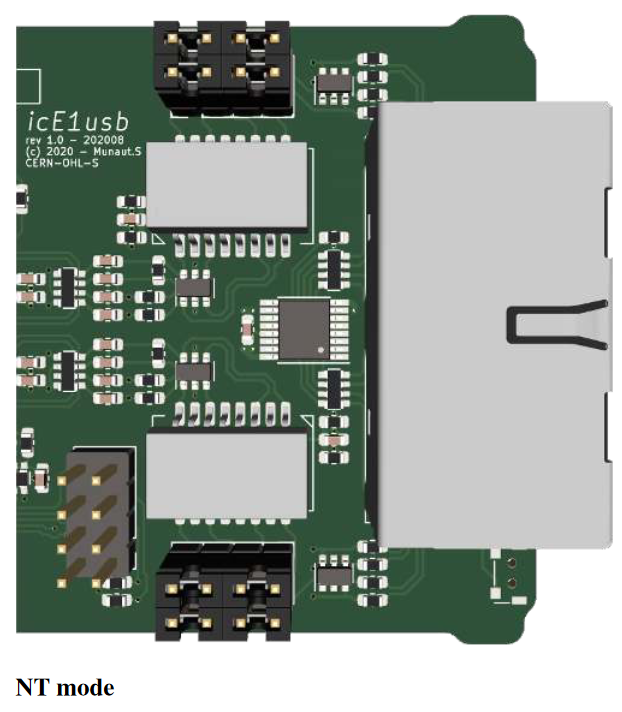
- Open up the icE1USB (from the back, with the SMA connector), and swap the jumpers so they match this picture:

CTS Setup
- Get a clear view of how the CTS is configured, and its necessary configuration files: bssparams.txt, set_x_gp, gm, sc, sub.csv, etc. Please make sure everything works as a standalone site before starting this entire endeavour!
- You also need good way to remotely connect to the CTS management interface (VNC is a good option).
- Plan ahead and make a list of the BrandMeister TGs you want your CTS to handle. Add them already to set_x_gp and gm.csv, reboot everything and make sure they already work locally in standalone mode.
- Open up bssparams.txt on your CTS, and do the following edits. Don't change anything else at this state:
## Base-Station Parameters ################################################################ #### Set the name to something simple, short, no special caracters /base-station/name = "CTSBS"; #### set this to id 1 /base-station/base-station-id = 1; #### add or replace: /base-station/standalone-mode = false; #### add or replace: /base-station/use-local-site-fall-back = false; ## Air Interface BLE Parameters ########################################################### /base-station/BLE/neighbour-cells = 191; ## SDS Gateway Parameters ################################################################# #### Remove all other lines, replace by: /system/sds-gateway/host-1 = { issi = 262999; ip-address = "44.225.64.18";}; /system/sds-gateway/host-2 = { issi = 250999; ip-address = "44.225.64.19";}; /system/sds-gateway/host-3 = { issi = 16777184; ip-address = "44.225.64.20";}; # These ISSIs will be used for SMS and GPS services (via GWPC emulation, IP addresses don't matter) ## E1 Layout Parameters ################################################################### ### Remove all other E1 layout lines, and replace byt this: /network/E1-layout/time-slot-01 = { source-type = "SIGNALLING"; }; /network/E1-layout/time-slot-02 = { source-type = "SIGNALLING"; }; /network/E1-layout/time-slot-03 = { source-type = "SIGNALLING"; }; /network/E1-layout/time-slot-04 = { source-type = "SIGNALLING"; }; #### Real BS transceivers /network/E1-layout/time-slot-17 = { source-type = "BS"; base-station-id = 1; l-transceiver-id = 11; }; #### Dummy's emulated BS transceivers /network/E1-layout/time-slot-22 = { source-type = "BS"; base-station-id = 8; l-transceiver-id = 11; u-transceiver-id = 12;}; /network/E1-layout/time-slot-23 = { source-type = "BS"; base-station-id = 8; l-transceiver-id = 13; u-transceiver-id = 14;}; /network/E1-layout/time-slot-24 = { source-type = "BS"; base-station-id = 8; l-transceiver-id = 15; u-transceiver-id = 16;}; /network/E1-layout/time-slot-25 = { source-type = "BS"; base-station-id = 8; l-transceiver-id = 17; u-transceiver-id = 18;}; #### Dummy's emulated GWPC encoders /network/E1-layout/time-slot-26 = { source-type = "DISP"; }; /network/E1-layout/time-slot-27 = { source-type = "ISDN"; }; /network/E1-layout/time-slot-28 = { source-type = "ISDN"; }; /network/E1-layout/time-slot-29 = { source-type = "ISDN"; }; /network/E1-layout/time-slot-30 = { source-type = "ISDN"; }; ## Network Topology Parameters ############################################################ #### Remove all other network topology parameters, and replace by this. Don't forget to change CTSNAME to the same name as in line 3! /network/topology/gateway-pc = { name = "Gateway Server"; E1-connection-1 = "BS-8"; }; /network/topology/base-station-1 = { name = "CTSBS"; E1-connection-1 = "BS-8"; }; /network/topology/base-station-8 = { name = "DUMMY"; E1-connection-1 = "BS-1"; E1-connection-2 = "GW-PC"; }; - Save and reboot the CTS, make sure it still works.
- Copy bssparams.txt over to your local PC, you'll need it for your Raspberry Pi.
- Write down the IP address of your CTS BSC computer (mine was 10.10.15.31, but yours will probably be different).
Software Stack Install
- Prepare an SD card with a 64-bit Raspbian Bookworm (Debian 12)
- Update/Upgrade the OS after boot:
sudo apt update && sudo apt upgrade reboot - Add the Osmocom repo, as per Osmocom's documentation:
sudo su OSMOCOM_REPO="https://downloads.osmocom.org/packages/osmocom:/latest/Debian_12" wget $OSMOCOM_REPO/Release.key mv Release.key /etc/apt/trusted.gpg.d/osmocom-latest.asc echo "deb [signed-by=/etc/apt/trusted.gpg.d/osmocom-latest.asc] $OSMOCOM_REPO/ ./" > /etc/apt/sources.list.d/osmocom-latest.list apt update - Install Osmocom E1D:
sudo apt install osmo-e1d - Add the TetraPack repository:
wget https://packages.tetrapack.online/install/public.key mv public.key tetrapack.asc sudo apt-key add tetrapack.asc sudo echo "deb [arch=arm64] http://packages.tetrapack.online/repository/ bookworm main" > /etc/apt/sources.list.d/tetrapack.list sudo apt update - Install TetraPack dummy and cts-logcollector
sudo apt install tetrapack-dummy cts-logcollector - Plug in the icE1USB to your Rpi, recover the interface serial number:
sudo lsusb -d 1d50:6145 -v 2> /dev/null | grep iSerial - Open (with for instance nano) /etc/osmocom/osmo-e1d.cfg, copy/paste this:
log syslog daemon e1d interface 0 icE1usb usb-serial [interface serial number] line 0 - Reload the service:
sudo systemctl restart osmo-e1d
Dummy - E1 Link setup
- Make sure Dummy is off with:
sudo systemctl stop dummy@default.service - Open/Create /opt/TetraPack/bssparams.txt, and copy/paste the contents from the file created at the CTS setup step. Edit the following lines
## System Parameters ##################################################################### ### Edit/Replace /system/name = "DUMMY"; ## Base-Station Parameters ################################################################ ### Edit/Replace /base-station/name = "DUMMY"; /base-station/base-station-id = 8; - Open/Create /opt/TetraPack/default.env
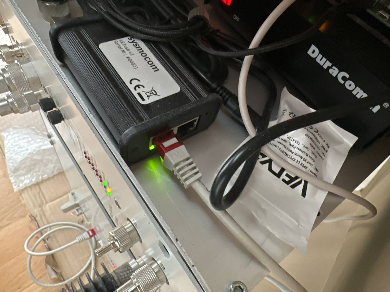
# E1D interface and line in format [interface number].[line number] DUMMY_LINE=0.0 # Path to CTS topology file (bss3.txt or bssparams.txt) DUMMY_TOPOLOGY=/opt/TetraPack/bssparams.txt # IP address and mask for CTS VTUN interface DUMMY_NETWORK="192.168.0.8 mask 255.255.255.0" # Specific options (multiple values can be delimited with comma): # replace-forwarded-link-status - replace IP-forwarded status for both E1 lines status of local BSs/GWPC to up # emulated-bs-line1-down - set E1-1 status of emulated BS to down # emulated-bs-line2-down - set E1-2 status of emulated BS to down # emulated-gwpc-line1-down - set E1-1 status of emulated GWPC to down # emulated-gwpc-line2-down - set E1-2 status of emulated GWPC to down DUMMY_OPTION= # Server connection URI in format http(s)://[user]:[password]@[address]/[path and parameters] # If you care about securely stored password, please put credentials into /opt/TetraPack/.netrc (man netrc) # REPLACE <YOUR DMR-ID> and <YOUR HOTSPOT/REPEATER PASSWORD> with your radio ID and password :) DUMMY_CONNECTION="http://<YOUR DMR-ID>:<YOUR HOTSPOT/REPEATER PASSWORD>@core.tetrapack.online:8081/dummy/?mode=bs+gwpc" # Instance name for D-BUS IPC interface DUMMY_INSTANCE=default - Save everything, cross your fingers and connect E1.1 from your BSC to the left port of icE1usb, like so:

- The matching LED on the port should stop blinking, and the red LED on E1-1 should turn off.
- Try to start dummy from the console:
cd /opt/TetraPack ./run.sh default.env # First, read starup messages and check that configuration (default.env and bssparams.txt) parsed successfuly # Second, check connection: if you see, in blue, "Q.921 connection established", congratulations! Your E1 link works! # You should also see "Socket Connection Established" - this means, connection to server established - If everything works, Ctrl+C to stop the console instance, and enable the service + start it
sudo systemctl start dummy@default.service
LogCollector - CTS Management interface setup
- Connect the USB/Ethernet interface to the Pi, and connect an Ethernet cable from BSC management port to the usb dongle.
- Stop LogCollector:
sudo systemctl stop cts-logcollector@default.service - Set a static IP on the interface (probably eth1) on the same range as the BSC, by editing /etc/dhcpcd.conf and adding this:
# Don't forget to edit your ip address to match the range of your BSC! interface eth1 static ip_address=10.10.15.20 static routers=10.10.15.1 - Test if you can connect via telnet:
telnet [BSC IP ADDR] 51600 #If you get "220 Network Management Interface is ready.", you're good to go! - Through that telnet interface, you can check if you got a good E1 link with Dummy:
login a cd network netstat #Look at the table that pops up, and focus on the "Links" column #260-rsp #260-Node Links DD AI ISDN DISP #260--------------------------------------------- #260-BS-1 u - u u - - #260-BS-2 ? ? ? ? - - #260-BS-3 ? ? ? ? - - #260-BS-4 ? ? ? ? - - #260-BS-5 ? ? ? ? - - #260-BS-6 ? ? ? ? - - #260-BS-7 ? ? ? ? - - #260-BS-8 u u u u - - #260-GWPC d u u - u d #260- #260 . #BS-1 should have first link on U, BS-8 should have both U, and GWPC should have D U #If it's not the case, check the topology with: cd topology ls #Should show this: #260- d-- gateway-pc #260- d-- base-station-1 #260- d-- base-station-8 #If not, check your bssparams.txt on both the CTS and the Pi, something is wrong. - Close the Telnet session (Ctrl+c), open /opt/LogCollector/default.env, and change the ip address:
# [IP of basestation] [dummy instance name] [basestation ID (1-8)] COMMAND_ARGUMENTS=[YOUR BSC IP] default 1 - Enable/Restart LogCollector, wait for a bit and see if you get data coming from the CTS when you place a call or attach to a group:
sudo systemctl enable cts-logcollector@default.service sudo systemctl start cts-logcollector@default.service #Let's monitor syslog to see if it recovers logs from the CTS. You should see a bunch of lines show up. tail -f /var/log/syslog | grep cts - If it works, great! LogCollector is ready. Ctrl+C to quit tail, carry on to the rest
EBTS
Introduction
- No LST! (No Red Lights on TSC, and No Annoying Notification on the Front of your Radios)
- Network Wide Group Calling - TGS Configured in our Core are Routed between ALL Linked BTS Sites
- Local Site Private Calling - Having a Linked site allows for 1-1 Private Calling (NOT FULL DUPLEX). Simply Dial the ISSI Number of the radio you wish to dial and hit PTT, this will call the radio and establish a 1-1 Call
- Wide Area Private Calling - As Above, Just across the network! - Call your buddys across the world via their ISSI Number.
The aim of this guide is to help you get your EBTS connected to our Virtual Core, and enjoy all TETRA features (+ TPC interconnects, coming soon™).
Disclaimer
-
Follow this guide at your own risk! This is an experimental bridge, and we can't be held responsible if anything bad happens to your precious EBTS!
-
DEBIAN/RASPBIAN WITH A GUI IS NOT SUPPORTED! - PLEASE ENSURE YOU INSTALL DEBIAN LITE (NO GUI), THIS IS KNOWN TO CAUSE OUT OF RESOURCE BUGS WITH OSMO-E1D
-
Supplied Configurations for Cisco Connectivity are Examples/Known Working Configurations, it is down to the Site Sysop to Secure their own System from unauthorised access
Prep Work
- Before starting this endeavor, get in touch with the Core Network Team, you'll need some specific configurations files for your site (Cisco and EBTS)
- You must have a basic understanding of the TETRA standard (how it behaves, how to program radios with MCC/MNCs, add talkgroups).
- Modifications on the EBTS settings will also be needed, make sure you're also feeling at ease with that.
- Some Linux Console knowledge as well as basic Cisco usage will also come in handy.
Connection methods
Option 1 - Cisco router
- A working EBTS/MBTS setup in lone site trunking mode (bare minimum: Base Radio + Site Controller). Don't forget an RS-232/USB converter if your computer doesn't a native DB9 connector!
- Raspberry Pi. You can also use a Mikrotik router, but this is not documented here (you'll need to install and configure ZeroTier, and bridge it to a LAN port).
- Cisco 1900 / 2600 Series router + E1 Card (either one or two ports, both will work). You'll also need an additional Ethernet USB Dongle for the Pi. Make sure you also have a console cable.
- An E1 Crossover cable (RJ45 plugs). Schematic is as follows:
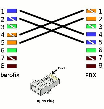
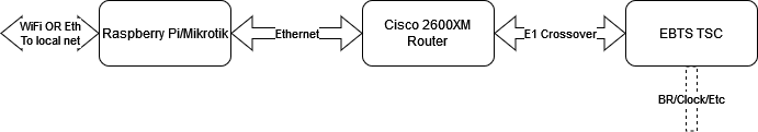
The complete setup will look like this:
Raspberry Pi Setup
- Prepare an SD Card with a 64-Bit version of Raspberry OS Lite(Bookworm being the latest, We Don't Need a GUI). Don't forget to configure SSH and WiFi if you plan to use it. You can also use an additional USB/Ethernet dongle instead of Wifi (you'll need an available ethernet port to connect to the Cisco Router either way).
- Update/Upgrade the OS after boot:
sudo apt get update && sudo apt upgrade reboot - Download and run the following configuration script. This will create the bridging interface, and add you to the ZeroTier network:
wget https://packages.tetrapack.online/install/tools/EBTS/CiscoBridge.sh | sudo bash - Connect the USB-Ethernet dongle if needed, and reboot. Connect the Cisco Router FastEthernet0/0 port to the dongle, and your WAN network to the Pi's onboard jack (or to the main Pi Ethernet jack if you're using Wifi to get online).
Sometimes the Pi will pick either the internal Eth or the Dongle Eth to be Eth0. If you notice that you cannot get a connection via your LAN to the Pi, try swapping the connection to the Cisco over.
Cisco Router Setup
- Connect your computer to the Console port of the router (via either an USB/RS232 adapter or a native DB9 port if you're lucky enough to still have one). Open up your favourite terminal program (I personally use putty) at 9600 baud.
- Follow these steps to reset your router to factory defaults.
- Once you finish step 8 on this before-mentioned guide, type "no" then enter.
- Check your Firmware Version:
show version Cisco IOS Software, C2600 Software (C2600-IPBASEK9-M), Version 12.4(12), RELEASE SOFTWARE (fc1) is Required - If you see any other version than what's mentioned above, reach out to one of the Core Network Team to update it.
- Open the Cisco Router config file you received (see "Prep Work") and copy its content (Ctrl+C). Enable the console and enter configuration mode:
config t Ctrl+V (paste) end write mem - Once done, you should be able to ping the Core via:
ping 192.168.250.254 - Almost there! If for some reason your FastEthernet0/0 interface didn't go up, type:
config t
int Fast0/0
no shutdown
end
write mem
Option 2 - icE1usb interface
Please read article FrameRelay-over-E1 Daemon (FRED)
After FRED install please edit /opt/FRED/default.env and run following command:
sudo /opt/FRED/dimetra-setup.shEBTS Site Controller
- Connect a USB/RS232 (or native DB9, again) from your computer to the service access port of the TSC. Open up BTS Service Software (aka TESS), select Dimetra R8. Password is Sys*mgr123$%. Under Configuration ==> Direct Settings, make sure you selected the right COM Port.
- Select Connection ==> Connect Direct. Turn on the TSC and wait for it to boot up completely. If it's already on, just press on enter, you should get a prompt for a user/password. Defaults should be factory/factory.
- Select Upload Configuration, and download the latest file from the Site Controller. Once done, close the connection via Connection ==> Close Connection.
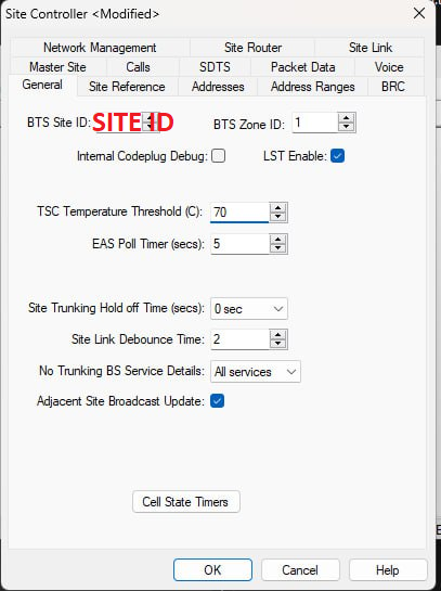
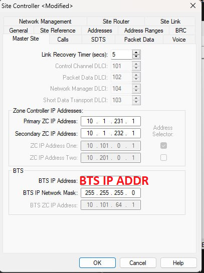
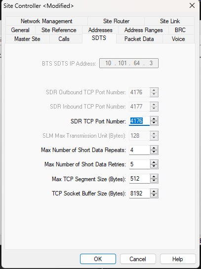
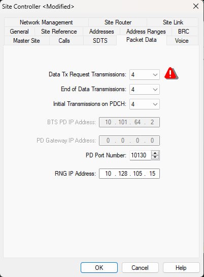
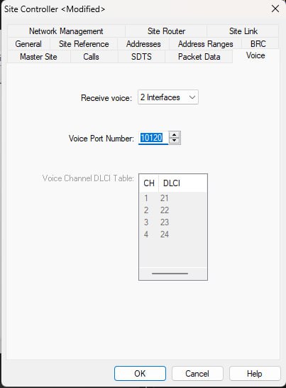
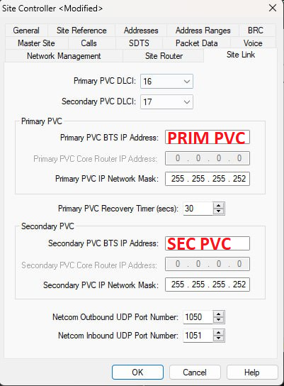
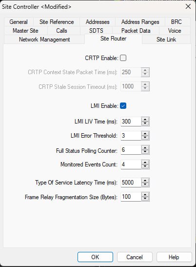
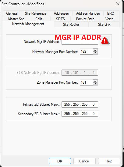
- Open the TSC Configuration file you just pulled via File ==> Open. Edit the Site Configuration via Personality ==> Modify. Click on "Edit Site Controller"
- From the Core Team, you should have received the following data: Site ID, BTS IP Address, PVC Primary, PVC Backup and Network Mgr IP Address. Make sure you have them close by, you'll need them now.
- Check your configuration matches the screenshots below, and copy over your site-specific data:


- Once you're finished, double check everything. Save the file, and reconnect to the TSC (Connection ==> Connect Direct).
- Click on Connection ==> Send Files. Select "Configuration Files" and select the file you just saved. In the “File Download” window, enter a version label, check “Use Next” and click on “Update Selected Items”. Press OK to start the transfer. You'll get a prompt to select which configuration file to replace. Select the one with all the minus signs.
- Remember when uploading the new configuration to update the "Use Next" Flag
- Reset the TSC by issuing the "reset" command on the terminal. Wait for the reboot, and log yourself in again (with factory/factory)
- Type the following commands to enable Site Link:
.sitelink -e1 .e1config -crdStart 1 -crd 31 -ts16Skip off -portNo 1 -crc on reset - After reboot, your TSC should now be connected to the Core Network! Enjoy :)
Final Steps
Once you have connected your BTS to the Core Network, Please go to https://map.tetrapack.online and register your user.
When an admin approves your user, you can log in and add your BTS to the map!
You will need the following information available when registering your BTS:
Zerotier Client ID: you will get this when setting up your Pi for Either Cisco or FRED configuration.
TX Frequency
RX Frequency
Duplex Table
Duplex Spacing
Once the BTS is approved by an Admin it will appear automatically on our BTS Map!
Cable Management Mod for Option 1
I found it quite convenient to put the Pi inside the empty Primary Network Module slot. A small mounting plate with double sided tape, another one for the USB/Eth dongle, and it's already much cleaner!
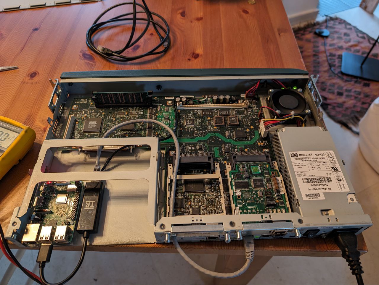
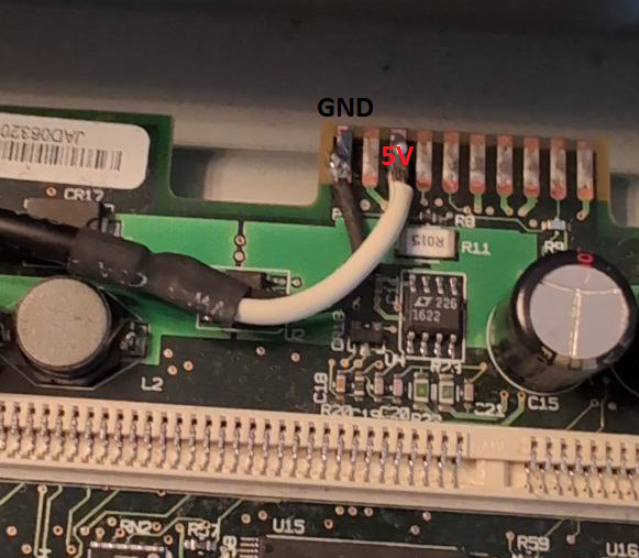
Bonus points if you use the Cisco Router's power supply to supply 5V to the Pi! Just solder a couple of wires on the edge card connector at the front of the router's mainboard. Leftmost pin is GND, then 12V (don't solder there!) then 5V. Double and triple check with a multimeter before hooking the Pi up.
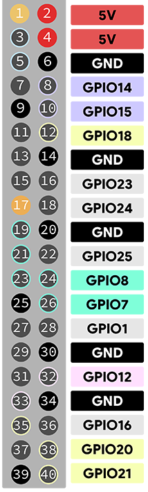
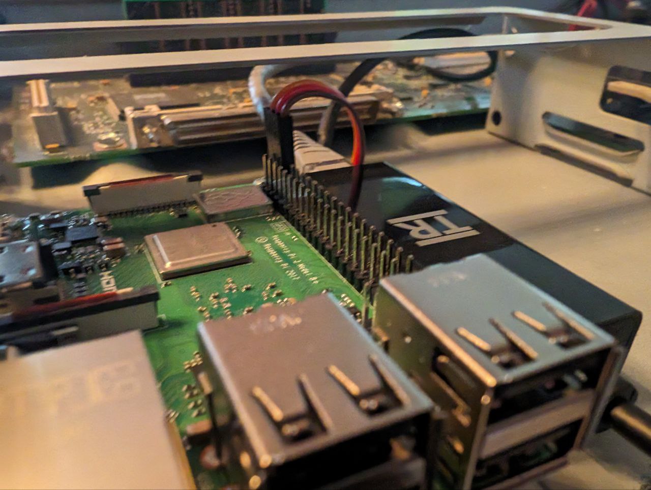
Pins 2 and 6 on the Pi can respectively be used as 5V and GND. An old servo connector does the job quite well!
Dummy
Intro
- Gateway software to run on on-site E1 connection (see article E1/T1 Interface)
- Transmits application-level messages between CTS E1 and TetraPack Core
- Decodes/encodes full signalling stack:
- E1 handler \
- HDLC FSM - (normally done by IC on BSC411 board)
- Q.921 FSM /
- Inter-site Connect transport including priority management (normally done by ISCD2.EXE)
- Decodes/encodes E1 and pre-buffer carrier streams (normally done by BSC411/TR412 boards)
- Partially emulates BSS.EXE/GWS.EXE (presence / status updates)
- VTUN over E1 between CTS and host (does not forward to the server)
- Uses the same bss3.txt configuration file as a base-station
- Has additional D-BUS API to pass specific data types such CTS logs to the server
- Debian 11 arm64 or amd64, tested on Raspberry Pi 3*, CM4 and Intel x64 PC
- Typical IP bandwith 4-100 Kbits/sec
* Some revisions of Raspberry Pi 3 have issues with icE1usb connection stability due to USB NIC
Configuration
Default configuration file is /opt/TetraPack/default.env
# E1D interface and line in format [interface number].[line number]
DUMMY_LINE=0.0

# Path to CTS topology file (bss.txt or bssparams.txt)
DUMMY_TOPOLOGY=/opt/TetraPack/bssparams.txt

# IP address and mask for CTS VTUN interface
DUMMY_NETWORK="192.168.0.8 mask 255.255.255.0"

# Specific options (multiple values can be delimited with comma):
# replace-forwarded-link-status - replace IP-forwarded status for both E1 lines status of local BSs/GWPC to up
# emulated-bs-line1-down        - set E1-1 status of emulated BS to down
# emulated-bs-line2-down        - set E1-2 status of emulated BS to down
# emulated-gwpc-line1-down      - set E1-1 status of emulated GWPC to down
# emulated-gwpc-line2-down      - set E1-2 status of emulated GWPC to down
DUMMY_OPTION=

# Server connection URI in format http(s)://[user]:[password]@[address]/[path and parameters]
# If you care about securely stored password, please put credentials into /opt/TetraPack/.netrc (man netrc)
DUMMY_CONNECTION="http://xxxxxx:password@core.tetrapack.online:8081/dummy/?emulation=bs+gwpc"

# Instance name for D-BUS IPC interface
DUMMY_INSTANCE=default
Connection URL
Parameters:
- emulation
- bs - tells Core to emulate basestation, required to deliver group and private calls. Emulated basestation will use ID from topology file (/base-station/base-station-id)
- gwpc - tells Core to emulate GWPC, required to forward SMS, location, etc. Please don't use if you have GWPC on-site
Topology
bssparams.txt is used to map CTS system topology and E1 layout as well as a system configuration. Parameter /base-station/base-station-id is used as identifier of emulated basestation (identifier of GWPC is hardcoded in CTS).
A capacity (amount of concurrent calls) of emulated basestation depends on amount on configured virtual transceivers for this basestation. Capacity = [count of transceivers] * 4 - 1
Please keep in mind that due to specific of CTS system topology must me configured as a chain of nodes, connected end-to-end. For example if you have two physical BSs, topology file has to be configured in scheme BS1 <-> BS2 <-> emulated BS <-> emulated GWPC. Regarding to this scheme you have to have properly configured termination endpoint in the main configuration (.env):
# emulated-bs-line1-down        - set E1-1 status of emulated BS to down
# emulated-bs-line2-down        - set E1-2 status of emulated BS to down
# emulated-gwpc-line1-down      - set E1-1 status of emulated GWPC to down
# emulated-gwpc-line2-down      - set E1-2 status of emulated GWPC to down
DUMMY_OPTION=emulated-gwpc-line1-down
Multiple instances
You can have several separated CTS systems connected to one or more core servers (for example, production and test). For such case you need to have several .env files for each configuration. use sudo ./setup.sh install to register all instances.
Also it's possible to run dummy in command line - sudo ./run.sh <configuration.env>
CTS Log Collector
CTS Log Collector is an additional software for Dummy. It connects to CTS basestation via TCP to logging ports and forward log entries to locally installed dummy.
The need
CTS Log Collector does following important things:
- gets GSSI attachments (Scan List) information from logs and passes to the core - required to manage group routing (no such data in signalling)
- passes log to logging server to simplify analysis of issues
Configuration
# [IP of basestation] [dummy instance name] [basestation ID (1-8)]
COMMAND_ARGUMENTS=10.0.0.1 default 1
MTS
Motorola's MTS Series of Tetra Base Stations are currently supported in TetraPack.
Installation
curl http://packages.tetrapack.online/install/tools/MTS/mts-setup.sh | sudo bashCTS Updater
CTS Updater (update-cts.py) is a small script to upload and update CTS configuration or database remotely and without restart. Better to run it on the same Linux system where dummy runs.
Utility creates index data, starts specific embedded ftp server, connects to CTS and initiates update. After updating it stops.
Installation
sudo apt install python3-pip python3-pyftpdlib
sudo pip install telnetlib3
Please make sure, you don't use firewall between your CTS and Linux. Also please make sure you have no ftp servers run on Linux system or use port TCP 21.
Usage
$ sudo ./update-cts.py <IP-address of CTS> [db|cfg] <path to folder>Exit codes:
- 0 - Success
- 1 - Error on Linux system
- 2 - Error on CTS system
Update database
$ ls db1/
sum-gm.csv sum-gp.csv sum-sc.csv sum-sub.csv
$ sudo ./update-cts.py 10.2.0.10 db db1 ; echo $?
Update configuration
$ ls -l cfg1/
bssparams.txt
$ sudo ./update-cts.py 10.2.0.10 cfg cfg1 ; echo $?
CTS
Motorola CTS-x00 is a series of basestations for CompactTETRA product line of Motorola. Literally its OEM-product of DAMM with software from Frequentis.
Following articles is about how to connect it to TetraPack:
SmartConnect
Configuration Guide
This guide explains how to configure SmartConnect on supported Motorola MXP600, MXP660 and MXM600 radios for use with TetraPack
The instructions assume the user has already purchased the "SmartConnect" feature license and has compatible firmware installed on the radio.
Requirements
Before configuring SmartConnect, ensure the following prerequisites are met.
Radio Requirements
The radio must have:
-
SmartConnect feature licensed
-
Firmware MR2025.2b or newer
-
Working Wi-Fi capability
- MS Authentication DISABLED
Software Requirements
Configuration requires:
-
Motorola Tetra CPS Plus 8.4 or newer
Network Requirements
The radio must have access to the internet via Wi-Fi and be able to reach TetraPack Core.
Endpoint
The TetraPack endpoint is:
![]()
REMEMBER - If your Hotspot Password contains Special Characters, these need to be entered into CPS URL Encoded.
For Example.
P@ssw0rd! = P%40ssw0rd%21
Radio Configuration (CPS)
Open the radio configuration in Tetra CPS Plus 8.4.
Step 1 – Configure Wi-Fi
Create a new Wi-Fi profile and configure:
-
SSID
-
Security mode
-
Password
Write the configuration to the radio.
Step 2 – Configure SmartConnect
Within CPS, configure the SmartConnect connection parameters.
Enter the TetraPack endpoint:
REMEMBER - If your Hotspot Password contains Special Characters, these need to be entered into CPS URL Encoded.
For Example.
P@ssw0rd! = P%40ssw0rd%21
Write the configuration to the radio.
Troubleshooting
If the radio fails to connect to the gateway, the most common cause is a cached certificate or invalid SmartConnect Certificate.
Reset the SmartConnect certificates using the radio Test Mode.
Enter Test Mode
On the radio keypad enter:
This opens the Test Mode menu.
Delete SmartConnect Enrollment Certificates
Delete the stored certificate.
After deleting the certificate:
-
Restart the radio
-
Reconnect to Wi-Fi
-
Attempt the SmartConnect connection again
Additional Notes
-
Radios must have a valid SmartConnect feature license installed.
-
Firmware older than MR2025.2b may not support the required connection methods.
-
Ensure outbound TCP connectivity to the gateway port is allowed.